Wendell Folks RV-8 Project - Page 61.
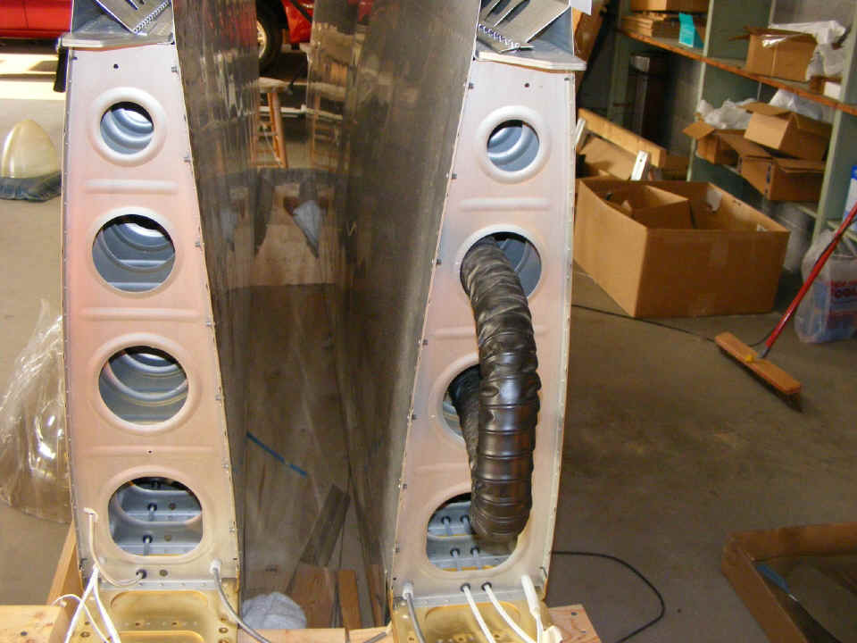
August 7, 2007: The wings needed some
K-1100-8 plate nuts at the wing root for attaching the wing fairings that will eventually
mate with the fuselage. This was a job Wendell wanted to do during the day when I
could not be there to guide him.
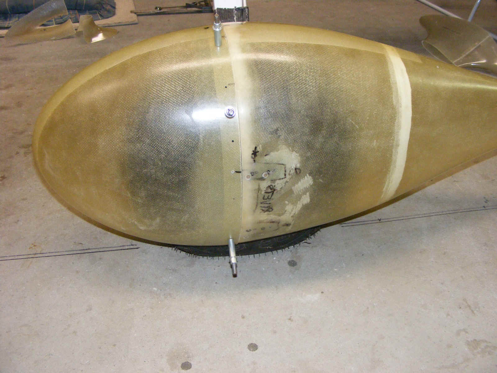
As for the wheel fairings, they are getting closer, but something is
still not quite right.
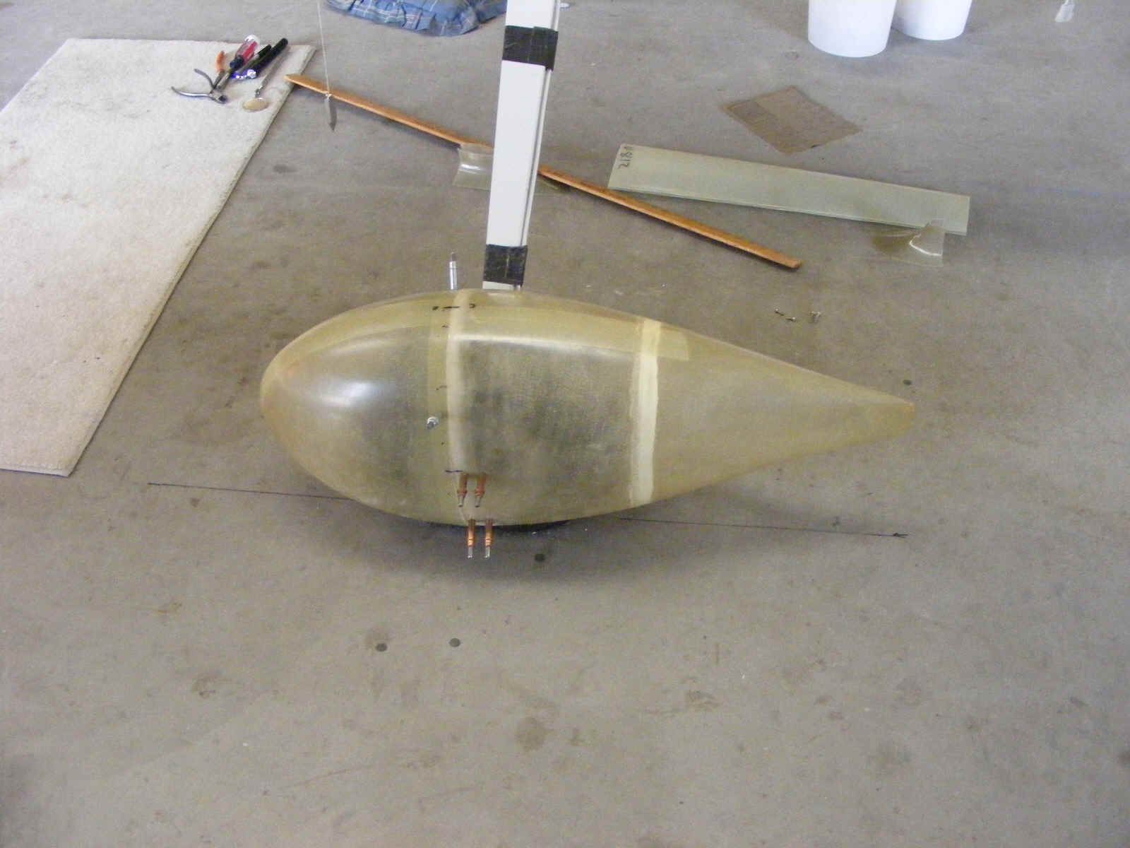
Back to grinding away a bit more of the fiberglass for proper tire clearance.
While Wendell was grinding away with the Dremel tool, I was looking at Van's blue prints for the wheel fairing on the RV-8 and comparing the similar print for my RV-9A. I found something on the revised RV-8 plans that was not on my RV-9A plans. Before you think there is something different in tail draggers vs. nose wheel airplanes, DON'T. The wheel fairings are put on to show proper orientation in level flight. What I found was an extra notation on the RV-8 print that said to jack up the airplane and take the load off the tire before measuring the pitch alignment of the wheel fairings. That note was not on my RV-9A print. In the end, it became apparent that the centerline of the wheel fairing had to also be aligned to be parallel to the floor for pitch, and parallel to the aircraft centerline to minimize drag and avoid any yaw conditions.
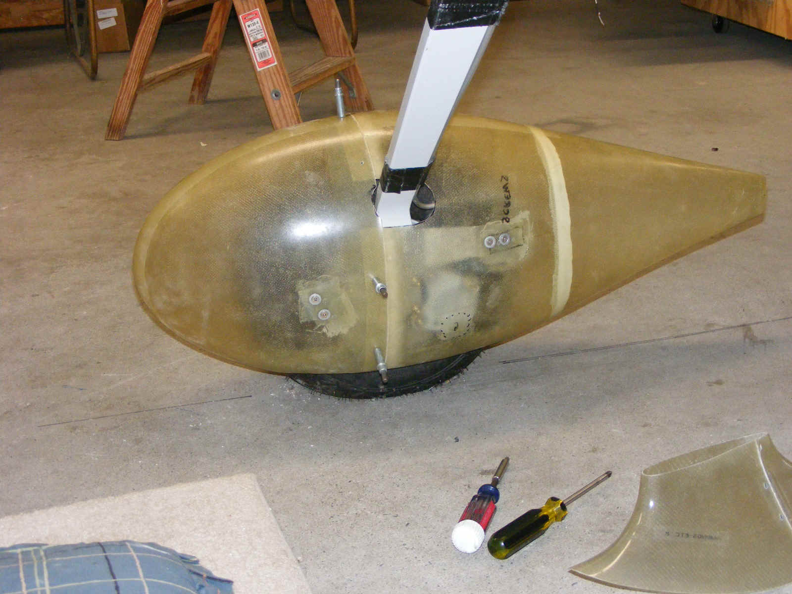
With that realization, it was obvious that my wheel fairings were probably installed incorrectly. We checked them and it was true. Now look at the second photo on this page. The nose of the wheel fairing is lower than the rear. What we did was to drill new holes in the sides of the main fairing and put in the clecoes again. The holes will need several layers of glass inside to allow the outer brace to be riveted in place with flat head rivets. The screw holes will also be reinforced. The new layers of fiberglass will cover the old holes that are in the wrong places.
As for fixing my wheel fairings, I probably won't worry about it since it would ruin my paint job. They are aligned parallel to the aircraft centerline to minimize yaw errors. I doubt that there is much in the way of excess drag to worry about.
After we got Wendell's main wheel fairings in the correct positions, I went to the tail of the airplane and measured how far off the ground the tail wheel is positioned. Then I moved over directly behind the main wheel fairings and put my eyes at the same height as the bottom of the tail wheel. From that position I could see how the wheel fairings would be positioned above the ground when the tail wheel is sitting on the ground. ALL is well!
August 25, 2007: Wendell and I got together for a Saturday session after all my travels on the road last week. If you look up the page two photos you see the left wheel fairing installed with clecoes. Wendell was not happy with the way they turned out in that previous session. He glassed over the holes from the inside and we aligned them again. One of the bolts that holds the brake caliper could touch the inside of the fiberglass fairing. We finally agreed that the alignment, although not perfect, would be implemented. The wheel fairing on the right side did not have the same close fit with the caliper bolt.
August 28, 2007: We
actually got together after a couple of nights of not working on the RV-8. The work
tonight is preparing hinges and the fiberglass gear leg fairings.
Wendell was working on the wheel fairings during the day today. He has
the metal brackets riveted to the outside of the wheel fairings. One bracket on the
outside of each wheel is secured by a 1/4x28 drilled bolt that will eventually get
safety-wired to the large cotter pin in the axle nut. You can see where additional
fiberglass layers were put inside the fairing where the rivets need to be countersinked
for the flat head rivets.
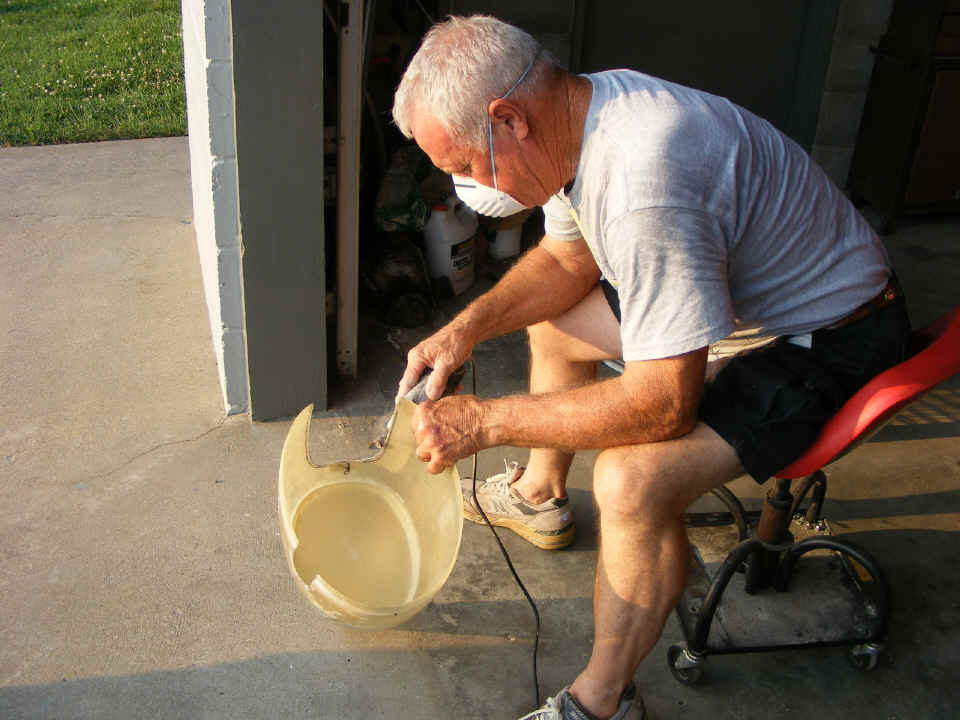
Here is the "inside" view of the right wheel fairing. Two pairs
of countersinked screws secure the fairings on the inside of the landing gear. Those
areas also needed extra layers of fiber glass to permit the countersinking of the glass to
accept tinnerman washers and 8x32 flat head screws.
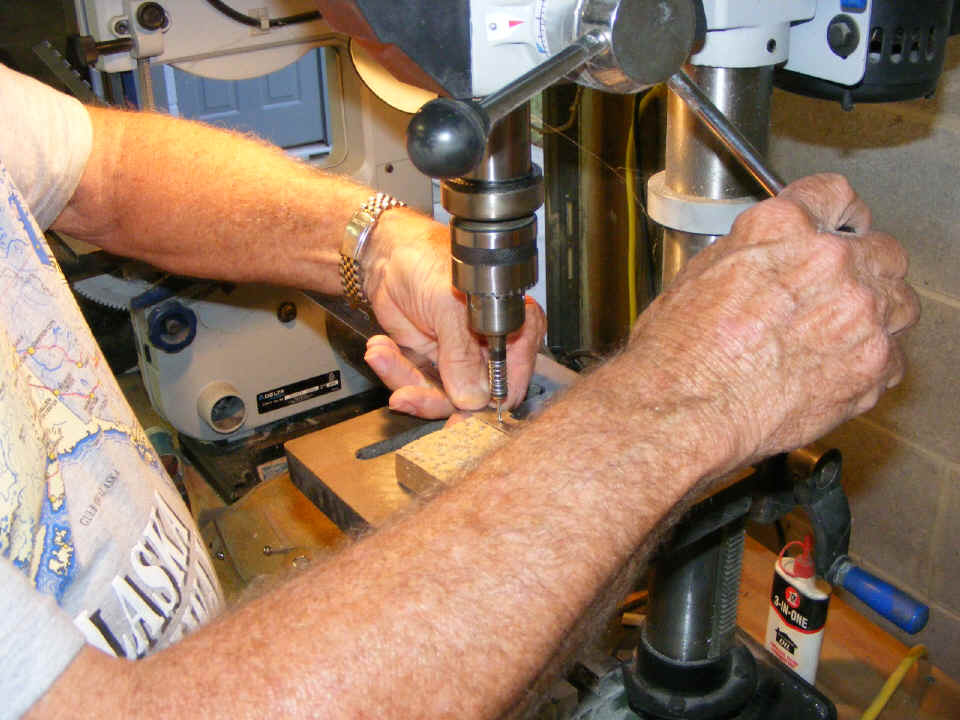
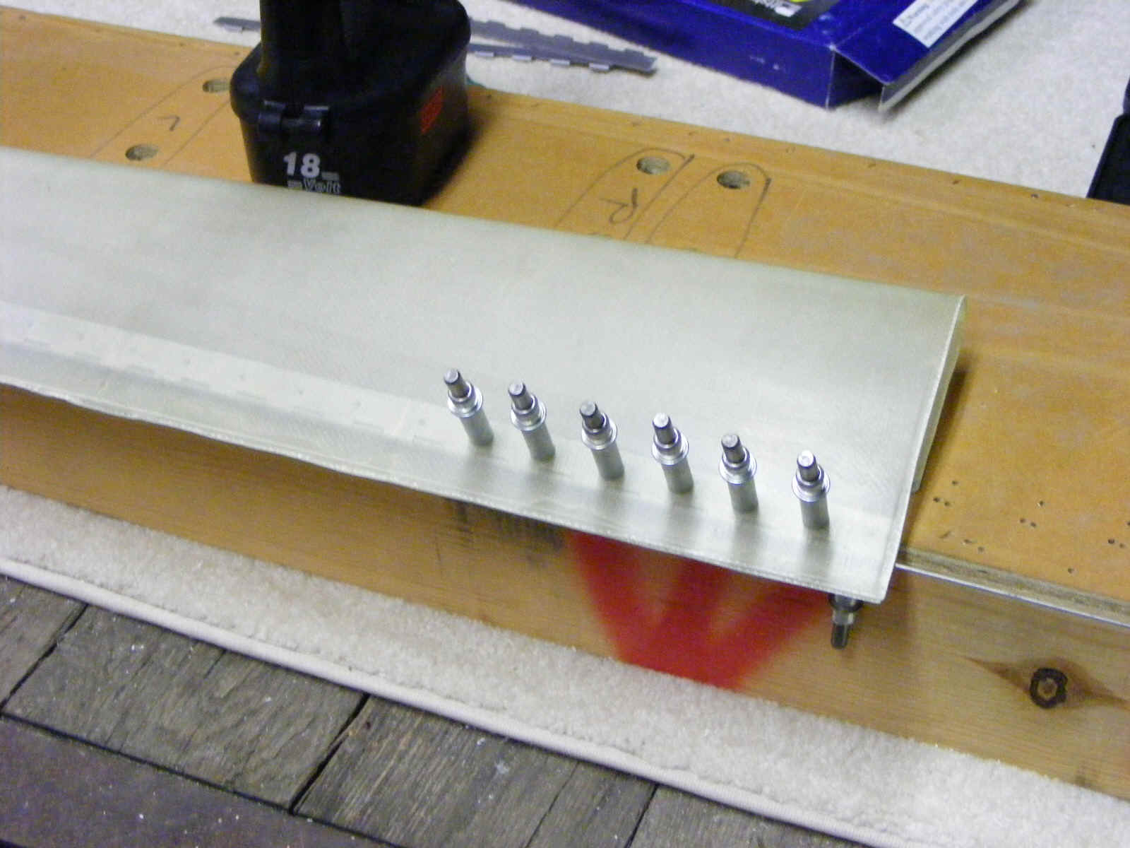
Here is one of the gear leg fairings with the pre-drilled hinges that are now
being match-drilled to the thin fiberglass fairing. The holes in the hinges are
spaced at 1-inch intervals. I brought out my old aileron/flap construction table
since it is the "flattest" work surface we had to insure the trailing edges of
the gear leg fairings would be straight.
| CLICK for Folks PAGE 62 | Return to Other RV Menu | Return to Main Menu Page. |