Wendell Folks RV-8 Project - Page 28.
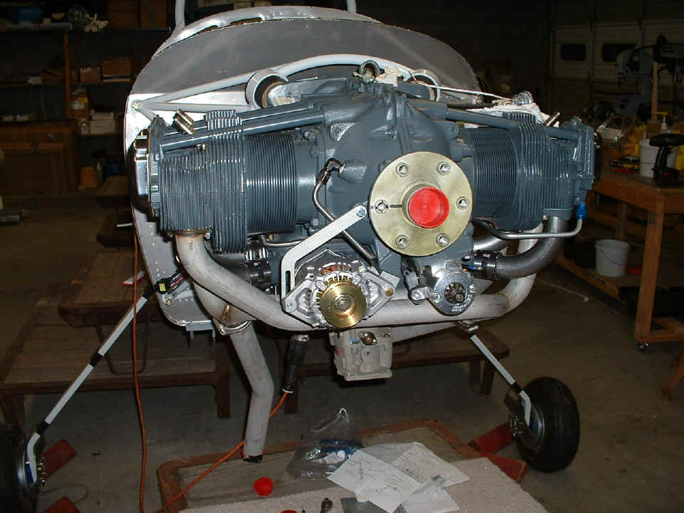
September 13, 2006: This was my last night
to review some things with Wendell before my road trip next week. You can see
he has been fitting the alternator and mounting bracket to the engine. He still has
some work to finish on that.
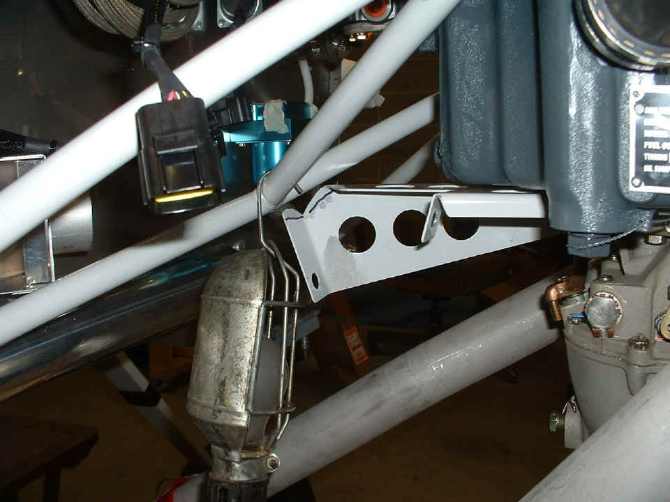
He has done some trimming on the steel bracket for the throttle and mixture
control cables. The bracket had clearance issues with the engine mount that needed
to be resolved. I marked the bracket for additional shaping to clear the mount.
September 18, 2006: I spoke to Wendell over the weekend while traveling. He reports removing the fuel pump and putting in the fuel fittings on each side of the pump for fuel line connections from the fuel flow sensor and going toward the carburetor. Since I am reporting this on the road, I don't have any photos to show you of that work. I did receive an email from an RV-8 builder regarding landing gear bolts. I need to review the photos of that work to provide an answer for him. Part of his question was about bolt torque values. Van's provides a table of bolt torque values in the front of the builders instruction book.
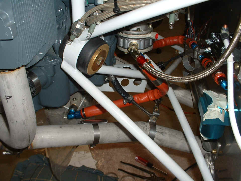
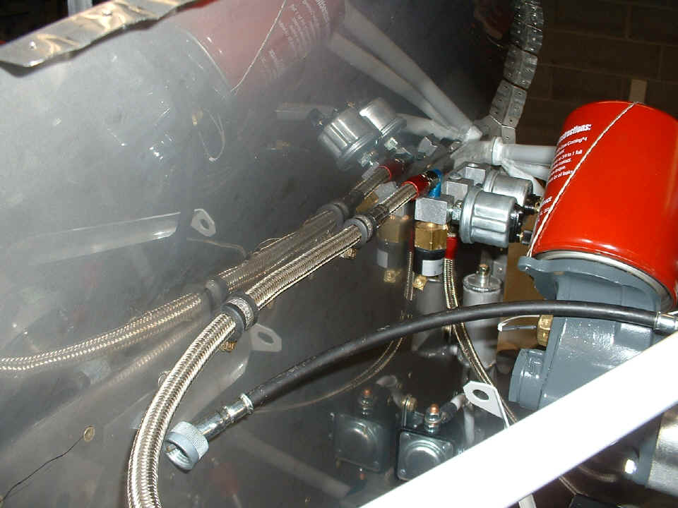
September 25, 2006: I visited
Wendell tonight to check on his progress with the RV-8 project. Here is a photo
showing the fuel hose connections to the fuel pump, carburetor, fuel pressure sensor, and
fuel flow sensor. Wendell had a custom fuel hose made to go between the gascolator
and the fuel flow sensor. I demonstrated how to build a mounting bracket for the
fuel flow sensor and the approximate location to mount it to the firewall. We also
measured the length of the fuel drain pipe needed for the gascolator.
Here is a better view of the fuel flow sensor and the short custom fuel hose to
the gascolator. When completed, the mount for the sensor will hold it solidly to the
firewall with a doubler plate on the inside. Unfortunately, there is no structural
angle behind that location on the firewall, since the rudder pedals are on the inside and
clearance for their movement is needed.
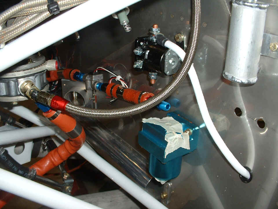
Here is the view of the oil pressure sensor hose running to the sensor
manifold. The Hobbs meter/oil pressure switch is installed along with the high
pressure sensor. You can see the oil filter extension has been installed at the
bottom right corner of the photo. The tachometer extension cable is ready to be
connected to the tach sensor. I indicated to Wendell where the tach sensor mounting
bracket needed to be mounted. The flexibility of the tach extension cable is the key
factor in mounting the sensor to the firewall.
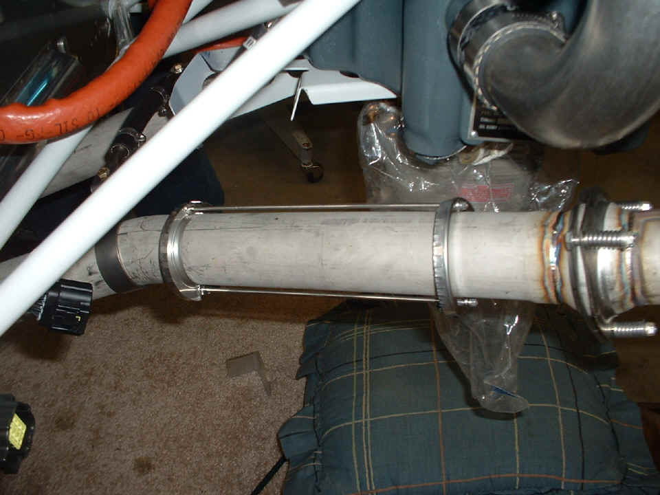
Over on the right side, the cabin heat muff will soon be installed. Here
is the muff support structure placed for an initial fit on the exhaust pipe. Those
pillows down there were used when I was examining the clearance issues for the throttle
and mixture cables and the exhaust pipe support linkages. We also experimented with
the routing of the red scat tube for the cabin heat vent door, etc. It is going to
be cramped in that area.
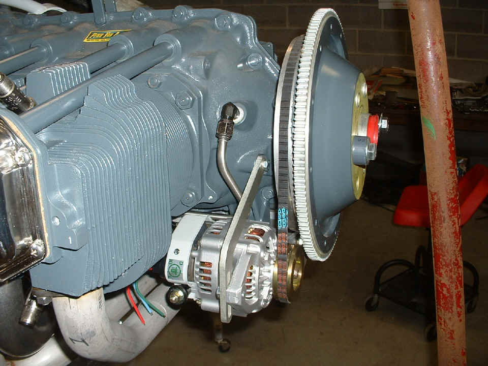
The last photo of the evening shows the alternator and the ring gear installed
with the v-belt to turn the alternator.
| CLICK for Folks PAGE 29 | Return to Other RV Menu | Return to Main Menu Page. |