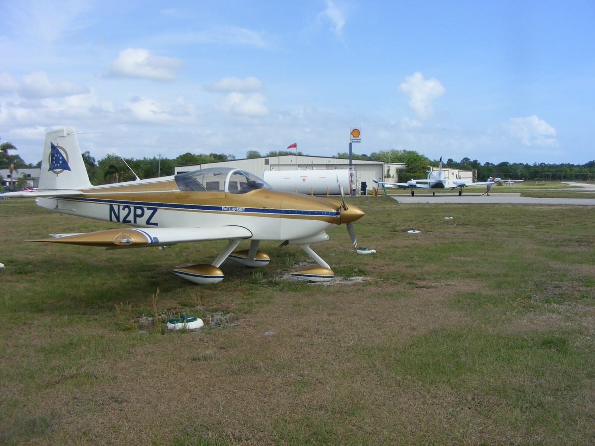
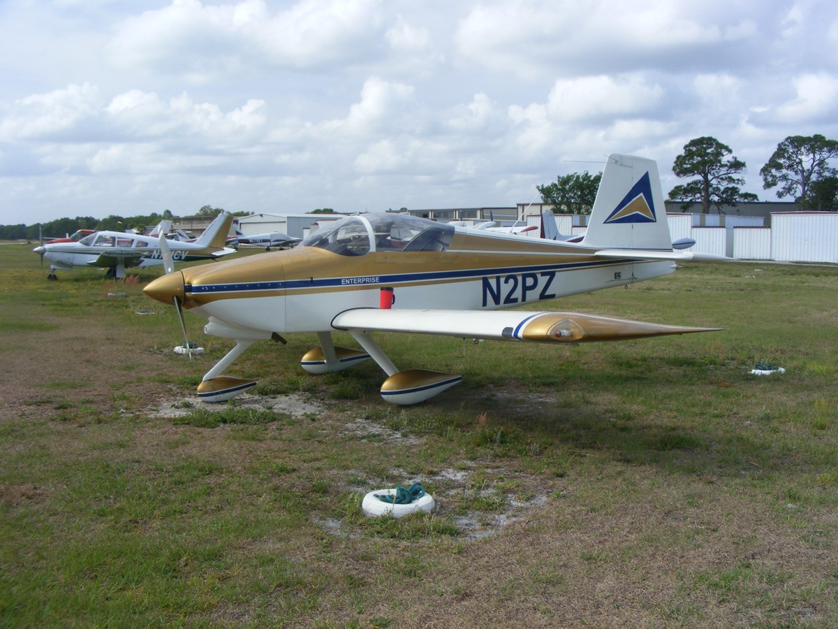
Spring 2017 in Florida · · PAGE 409.
April 8, 2017: I mentioned the changes made to the "KEEP ALIVE" wiring to my Dynon D-10A at the beginning of PAGE 408. That change to keep the Dynon internal battery charged is what drained the main battery in my airplane when someone had unplugged my battery charger. I had been thinking about putting a switch in series with that keep alive wire to prevent that from happening again. With as much down time my airplane had in the past year, the Dynon internal battery ran down since the avionics master switch is only turned on when the engine and avionics are in use.
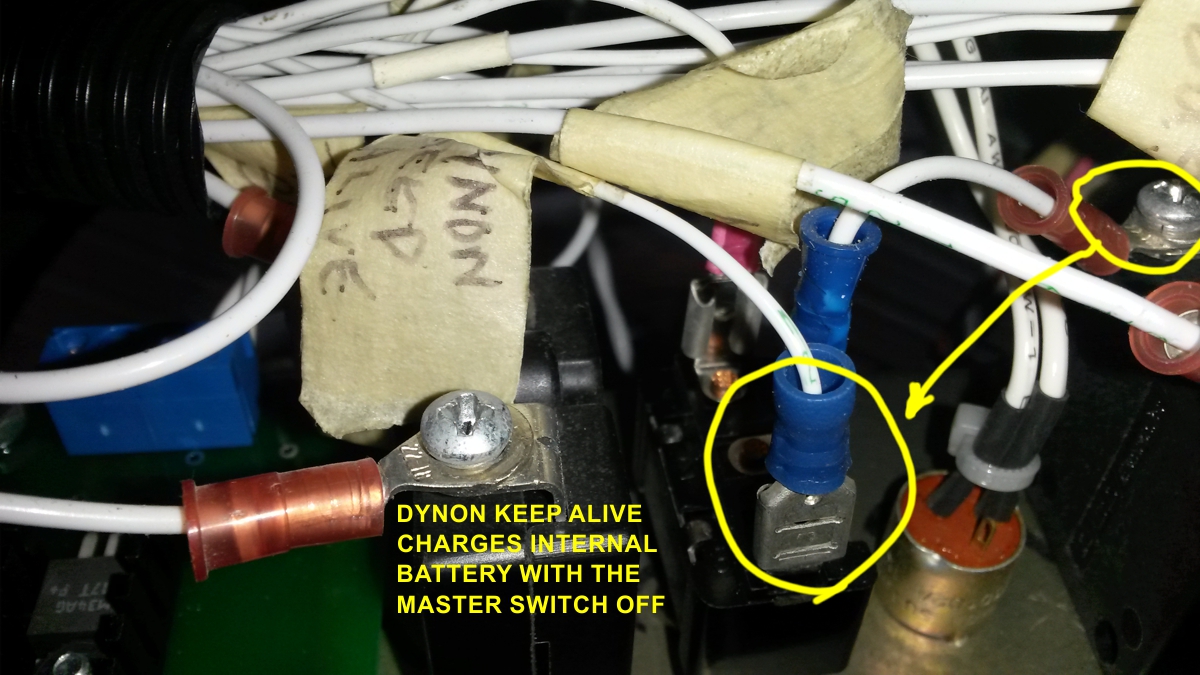
The Dynon internal battery can be recharged two ways, in normal use,
or via the keep alive connection. I have used one connection on my cabin
lights panel switch to connect the keep alive wire to the main battery bus when
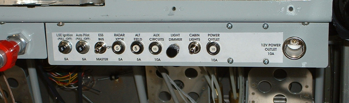
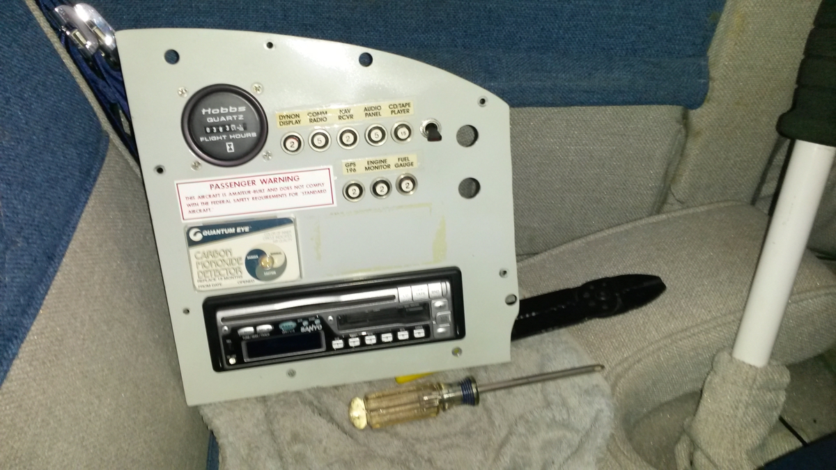
needed. Here is the switch panel where that change was made. This
image is cropped from an old photo taken when this switch panel was first
installed. When I put that single-pole, double-throw, center-off switch in the panel,
it was to operate the white LED lights in the baggage area for loading and
unloading the baggage area at night. I have used that feature only ONE
time at the Alliance Fort Worth airport in October 2005 on the way west to the
LOE5 fly-in. Pushing the switch from the CENTER OFF position to the DOWN
position powers those LED lights. The UP position on that CABIN LIGHTS
switch had no connection until today. I can turn that feature on only when
the airplane is going to be in long term storage like during the past year.
Here is what was done in close up photos from my cell phone. I
took this photo after moving the keep alive wire from the AUX CIRCUITS
breaker to the bottom terminal of the CABIN LIGHTS single-pole, double-throw,
center off switch. That moved wire is hidden in this image.
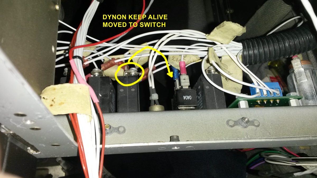
I realized the small size of my phone and the range of auto focus of
the camera in the phone can take photos I cannot do with my digital SLR
camera. The keep alive wire had a RING terminal on the end to attach to
the circuit breaker screw at the right edge of this image. I changed the
connector on the end of that wire to attach to a SPADE LUG. This whole
process was easy to do when I removed the switch panel from the main instrument
panel. When I had that panel in my lap, I found that DYNON KEEP ALIVE tape
label and realized I really did not need to remove either panel from the
instrument panel mounting frame. This extra work allowed me to refresh my
memory of how everything in the panel is connected.
Most of the time I spent doing this job was to remove my main
instrument panel and trace the wire from the Dynon power plug to the point where
the KEEP ALIVE wire connects to the 12-volt DC source. I also had to
remove the sub-panel with the CD/TAPE player, Hobbs Meter, and other circuit
breakers from the right side of the instrument panel frame. I did that to
let me pull on the KEEP ALIVE wire and find the other end of it. It was
back in early 2005 when I put in that wiring and did not remember where it went.
I had placed the instrument panel in the baggage area out of the way while I was
working up front. When I had finished the wiring change, I put the
instrument panel in the passenger seat until I could get back in the pilot seat
for the reconnection sequence. I put all these labels on this photo this Sunday morning
as I prepare to publish this new page to my web site.
That black handle switch with no label is the power switch that
isolates the power to the CD/TAPE player from the DC bus for the same reason I
had to put the switch on the Dynon keep alive wire. The clock and the
memory in the player is another current drain on the main battery even with the
master switch turned OFF. Those two empty holes on the right side of the
panel provide access to the headphone jacks on the passenger side of the main
panel. This photo was taken of the secondary panel in the pilot seat while
I was in the passenger seat.
I found this old photo when I was getting the panel wired up on May 3,
2005. When I first posted this photo in 2005, it was to show the
installation of microphone and headphone jacks for direct connection to the
Garmin AT SL-30 NAV/COM radio in the event of a failure of the audio
panel. Some other things to see here are the masking tape labels on
various cables and wires behind the panels. That wire with the label
"HOT, DIRECT TO BATT" connects to the AVIONICS MASTER circuit breaker
switch. Behind that wire, the altitude encoder is there with a STATIC AIR
plastic tube connection, and the DBM electrical connector with the data link to
the GTX-327 radar transponder. There are TWO RG-400 beige coaxial cables
with BNC connectors on the side of the electronic ignition control module.
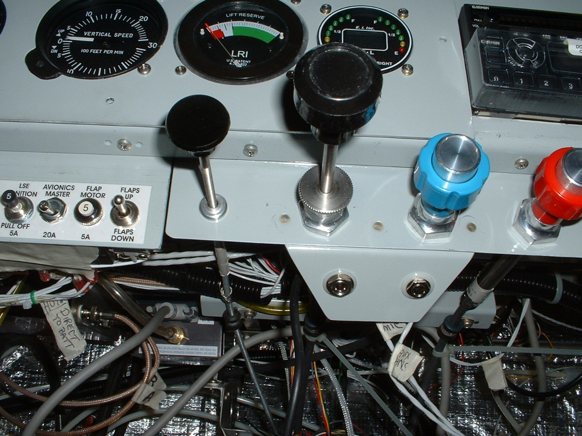
At the end of the work session, I powered up the AVIONICS MASTER switch
and confirmed the panel lit up with the normal indications. My passive air
connections from the STATIC AIR ports, PITOT TUBE, and the LIFT RESERVE air
probe all still have their labels on them and were connected to the instrument
panel correctly. Next week, I will get a chance to go flying to confirm
everything is working as it should.
One of the reasons I did not fly today was my 1 PM late arrival after lunch
since I was expecting strong cross winds of 15 to 20 knots from the ocean.
This was also the day when Bill returned from the SUN-N-FUN fly-in over at the
Lakeland Airport. Both of the ATEC light sport demo aircraft arrived here
at 11:30 AM. One of them was parked in front of my airplane again as it
was last week. I did not expect the airplanes to be here today. I
will fly my airplane next week and change the oil.
April 15, 2017: Today was the first time I have flown into Massey Air Ranch near Edgewater, Florida. It is a private airport open to the public. I learned the student pilots from Embry-Riddle University do a lot of flight training here since this is an uncontrolled air field. I looked at the weather conditions this morning before leaving home. The surface winds in this part of Florida today near the Atlantic Ocean are 15 to 20 MPH from the East. The runway at Rockledge is north/south. When I arrived in the parking lot, noticed the flag and judged the wind for myself. I departed on runway 36 and quickly felt the mild turbulence as I climbed above the tree line along the north end of the runway. When the trim and power settings were set, I glanced at the winds aloft on my Dynon D-10A and saw it rise to 30 MPH as I passed through 1000 feet MSL. I leveled off above 3000 MSL for the 45-mile ride up to the privately-owned Massey Ranch Airpark (X50) which is open to the public. My GPS 296 lists the flight up there as 23 minutes with a quartering tail wind. The return trip was 28 minutes with part of the trip facing those same winds. The southbound trip had me climbing up to 5,500 MSL to check out the winds further up and finding a smooth ride up there. The descent to Rockledge was dodging the broken cloud layer over the mainland as I followed the Indian River as I usually do when returning from points north of my home field.
Here are my usual photos when I land at an airport for the first
time. This is the first time these folks have had a pancake breakfast
hosted by one of the businesses on the property.
Being open to the public, they are selling fuel.
Here is a look toward the south with hangars in the background on the west
side of the runway.
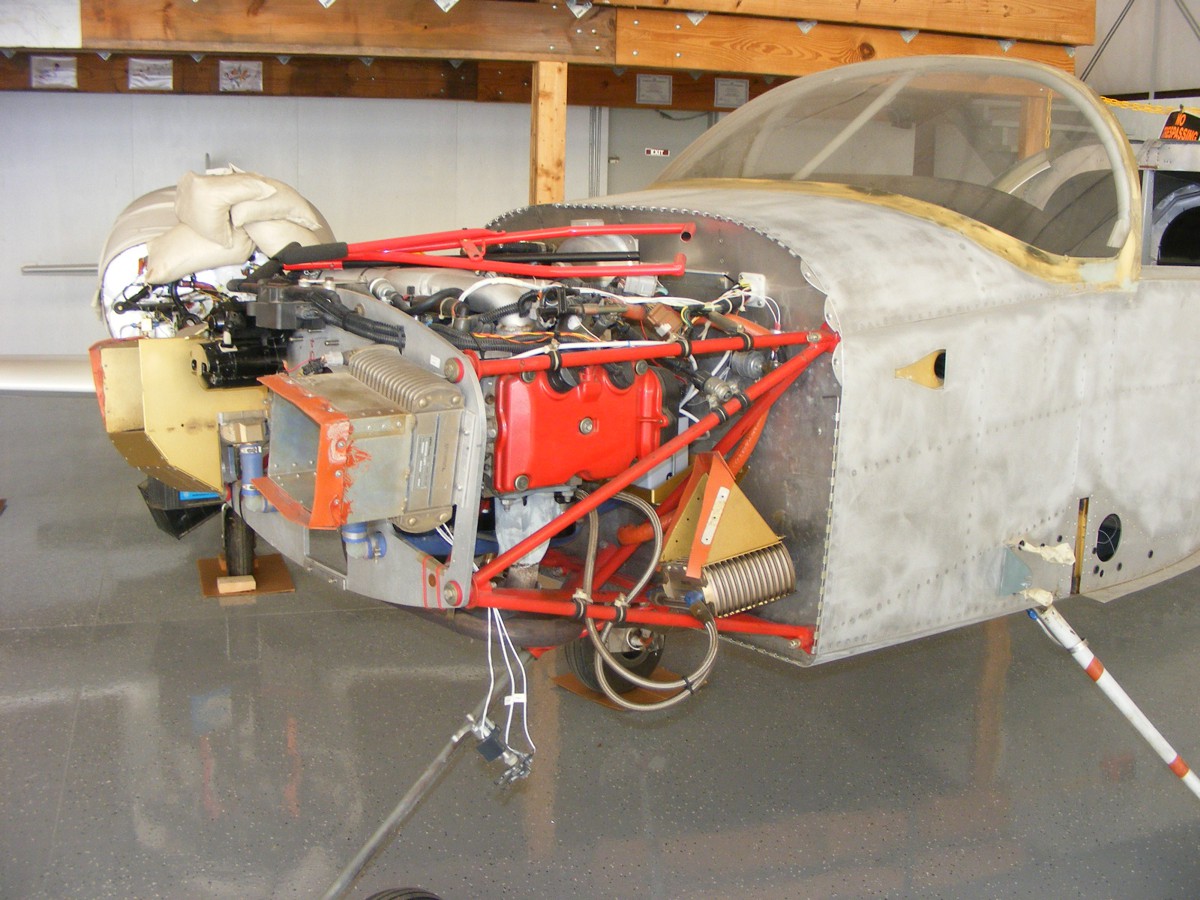
Several pilots asked me about my airplane. One of them purchased an
older RV-9A built in Texas with serial number 151 on the data plate and a Subaru
engine up front. The wings are removed at this time and being
painted. He took me down to a hangar where the fuselage was in
storage. The Subaru engine required a gear reduction drive unit which is
currently removed. The oil cooler is also removed from its normal location
up front under the center of the engine. It is temporarily hanging from
the engine mount near the firewall. There are two larger radiators up
front for engine cooling. The fuselage shows the sanding done prior to
painting. And if you are wondering about that engine mount, there is a
Bogert Aviation tow bar laying on top of the engine. I have one of those
"Bogie Bars" that is always in the airplane when I travel.
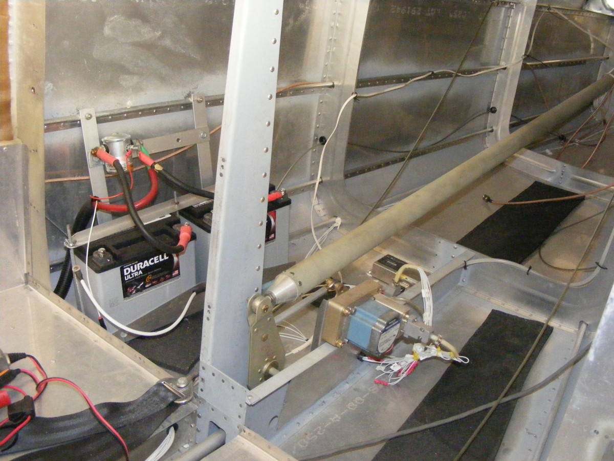
I took this photo behind the baggage area to show his elevator servo for
altitude hold. The heavier Subaru engine up front requires a couple of
batteries back here to keep the CG (center-of-gravity) in the proper range for
the air frame. He also has a Dynon D-10A in the panel with the remote
magnetic compass sensor mounted on the floor just aft of the servo motor.
The master switch solenoid is mounted above the batteries.
This page is being published on Sunday, April 16, 2017. I received an instant message from the owner of this airplane this morning. He sent me a photo of a part to identify for him. It did not look like anything I came across when I was building my airplane. He has all the blue prints, and he downloaded the assembly manual which has all the drawings for all possible options to build into an RV-9A. I suggested he search for that part in an option he does not have on the airplane. When I was building my airplane, Van's sent me a pair of parts for a tip-up canopy version that do not go into my slider canopy air frame.
The return to Rockledge had me watching the winds aloft at 30 MPH from the EAST as I was getting into the landing pattern. The winds became lighter the lower I got. I glanced at the Dynon reading when I was lined up with runway 36 to see about 14 MPH about 100 feet AGL on final approach. The crab angle was a good 20 degrees to the right before I used the rudder and aileron to line up the landing gear with the runway center line before touching down. I had carried a little extra speed on the approach expecting the cross wind to be lower as a result of the hangars on the East side of the runway. The roll out after landing was a bit longer, but not a problem. The proper landing technique for the RV-9A is roll on the main landing gear with sufficient UP elevator to keep the nose wheel off the runway as long a possible. The Hobbs meter added 1.1 hours today, with the total engine time for "Enterprise" now at 384.6 hours.
I will finish today's posting about my oil change back at Rockledge. I drained the oil and discovered the oil filter I had purchased back in November 2016 has the wrong thread size on it and needs to be returned for exchange. The airplane is back in the corner of the hangar with the cowling off of it awaiting the exchange of oil filters after the Easter Holiday weekend. They were ordered from Chief Aircraft and shipped from their Deland, Florida location, not too far away from here.
April 23, 2017:
This Sunday I had a chance to finish the oil change of the airplane with the
correct oil filter and AeroShell 100W aviation oil. I cleaned the aviation
spark plugs as I do at every 50-hour oil change. While those spark plugs
are OUT of the cylinders, spinning the engine using the starter is the safe way
to get oil into every part of the engine. After that, the airplane goes
outside to run the engine and see the oil temp and pressure come up
normally. After shut down, I check to see there are no oil leaks with a
clean paper towel touching all the vital places of the right-angle oil filter
adapter on the engine. I took this photo near the end of the day of
working in the hangar.
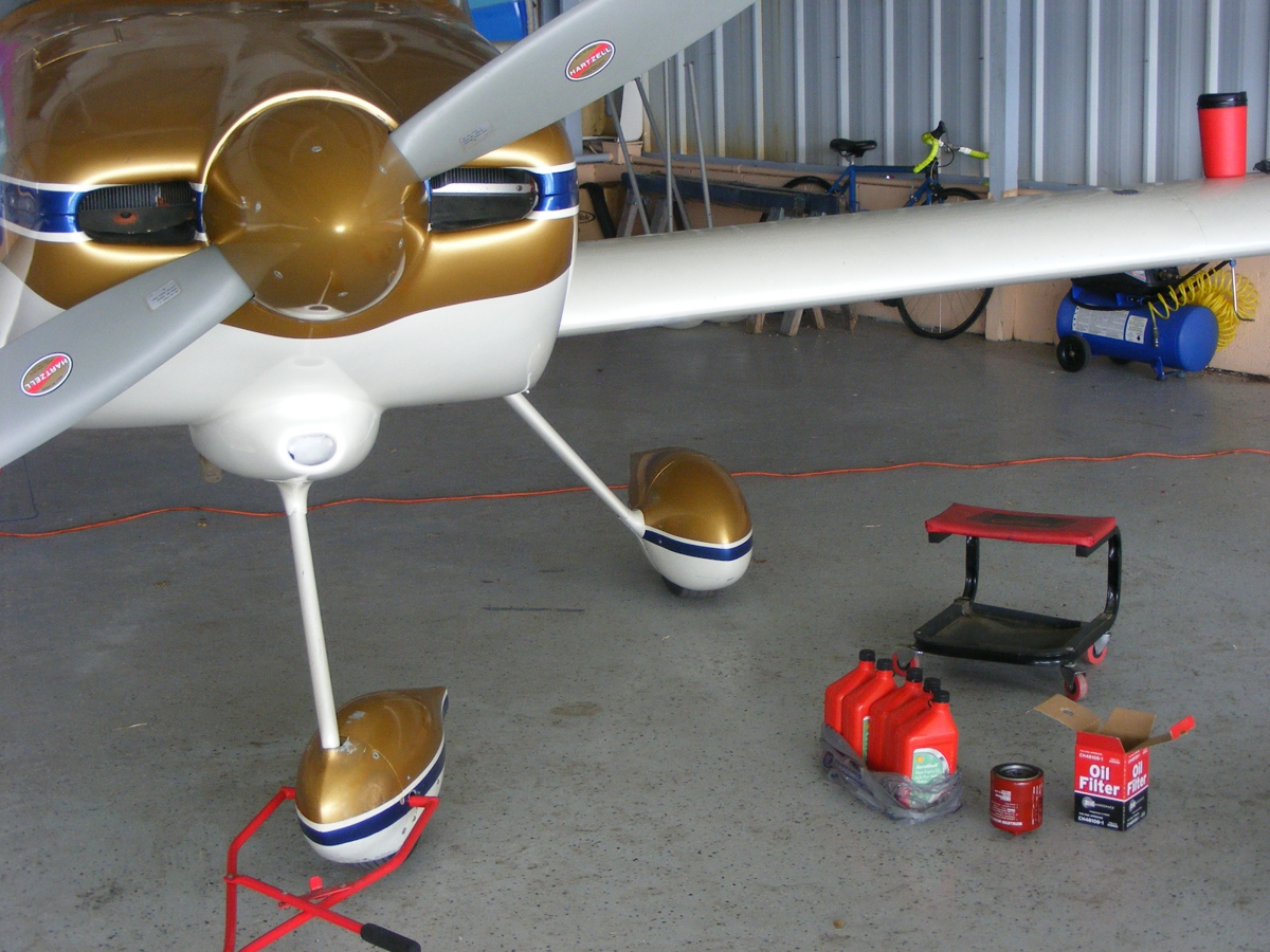
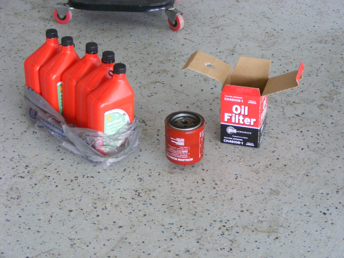
Here are the empty oil bottles and the old Kelly Aerospace oil filter are
ready to take out to the recycling center along with the oil I drained last
week, already in the trunk of my old 1996 Caddy. A new Champion CH-48108-1
oil filter is secured with safety wire and the airplane is ready to fly.
April 29, 2017: It was a good day to stay home and do some yard work on the sprinkler system. Bill Simmons said the wind at Rockledge Airport is blowing more than 20 MPH cross wind from the east. Spring time weather changes everything. One pilot who flew today said it was very bumpy even above the clouds.
| CLICK HERE for PAGE 410 | Return to MAIN MENU |