October 2010 · · PAGE 339.
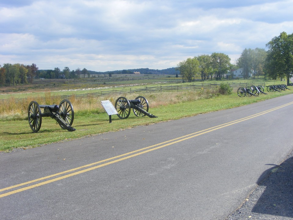
October 3, 2010: My trip from the Roanoke area to
Philadelphia took me through Gettysburg, PA. This trip I decided to drive through a
portion of the battlefield on the Gettysburg National Park. I felt right at home
since I live so near the Chickamauga Battlefield National Park.
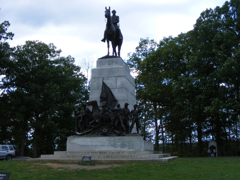
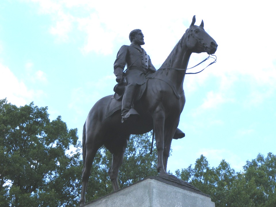
This monument has a bronze statue of General Robert E. Lee mounted on his horse
Traveler. The overcast conditions and the light from behind the monument made this
photo have high contrast.
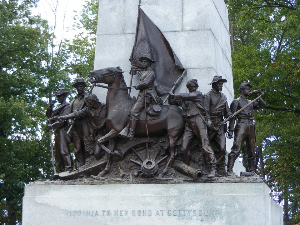
When I lowered my camera and got closer, the details of the large bronze near
the base of the monument are revealed.
I zoomed in on General Lee and processed this photo to wash out the background
to reveal the details of the bronze.
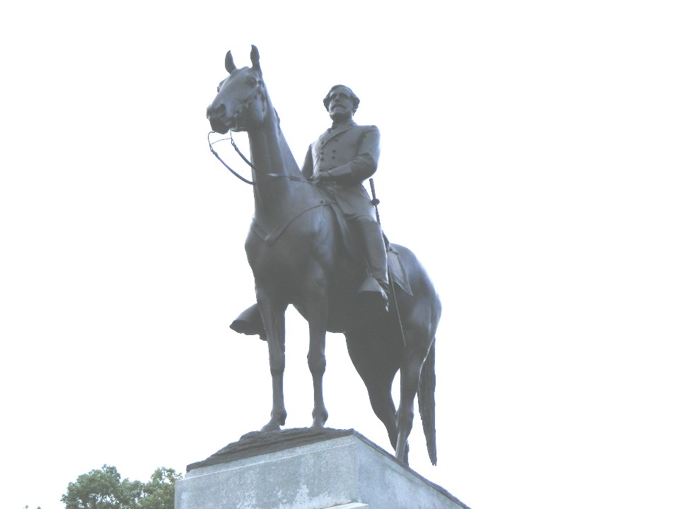
This second close-up photo provided some visible background and bronze details
after my post processing of brightness, contrast, and intensity. Since this monument
faces East toward the battlefield, it is best photographed in the morning sunlight.
I finished my brief driving tour of the battlefield and went over to York, Pennsylvania for a short visit with my son Jason and his family. The photos from that visit are in my family section of this web site.
October 4, 2010: I spent the day with my largest distributor of products from my day job. It was all about introducing some new products and training two of their new employees on the entire product line from the company that is my day job.
October 5, 2010: I had another call on
Tuesday morning in a nearby town before heading south for lunch in Baltimore near the
eastern beginning point of Interstate highway 70. I made it a point to drive east
from the beltway around Baltimore to get on the freeway near the actual starting point of
I-70 heading west out of town.
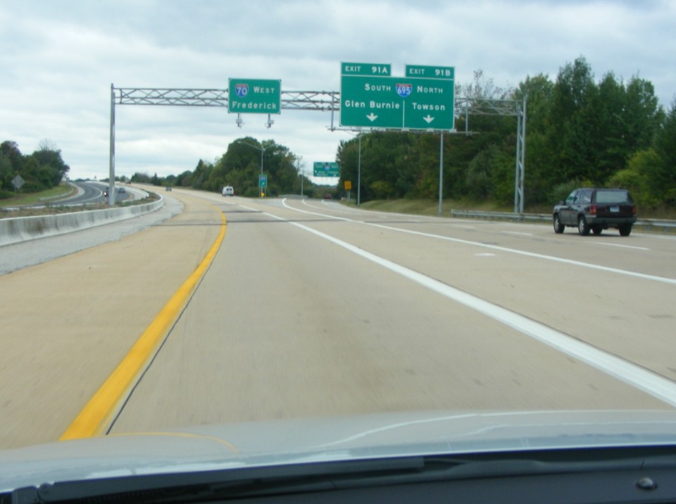
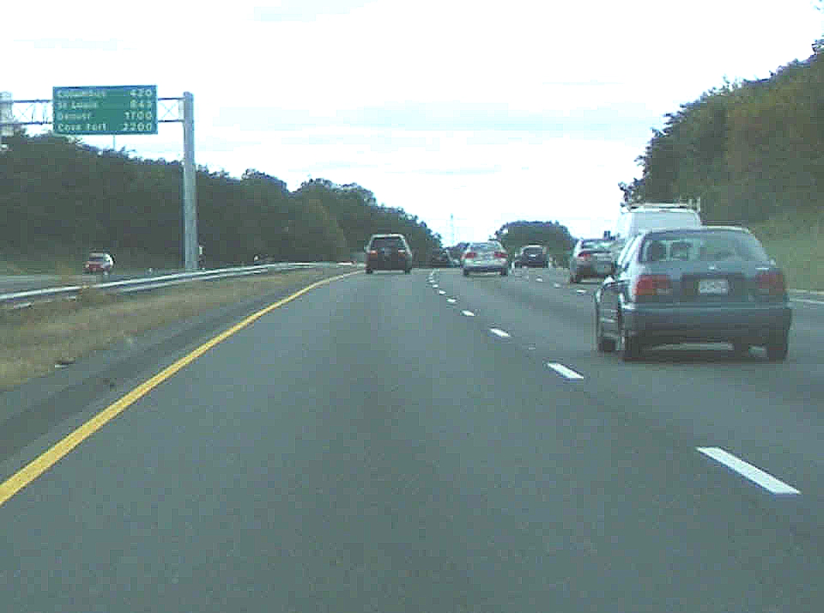
Just about a mile west of I-695, there is the sign that tells about the major
cities along the route of I-70 westbound to the ending point at Cove Fort, Utah where the
highway ends at its junction with Interstate 15. The towns listed are Columbus, Ohio
- St. Louis, Missouri - and Denver, Colorado with the last entry on the sign for Cove
Fort.
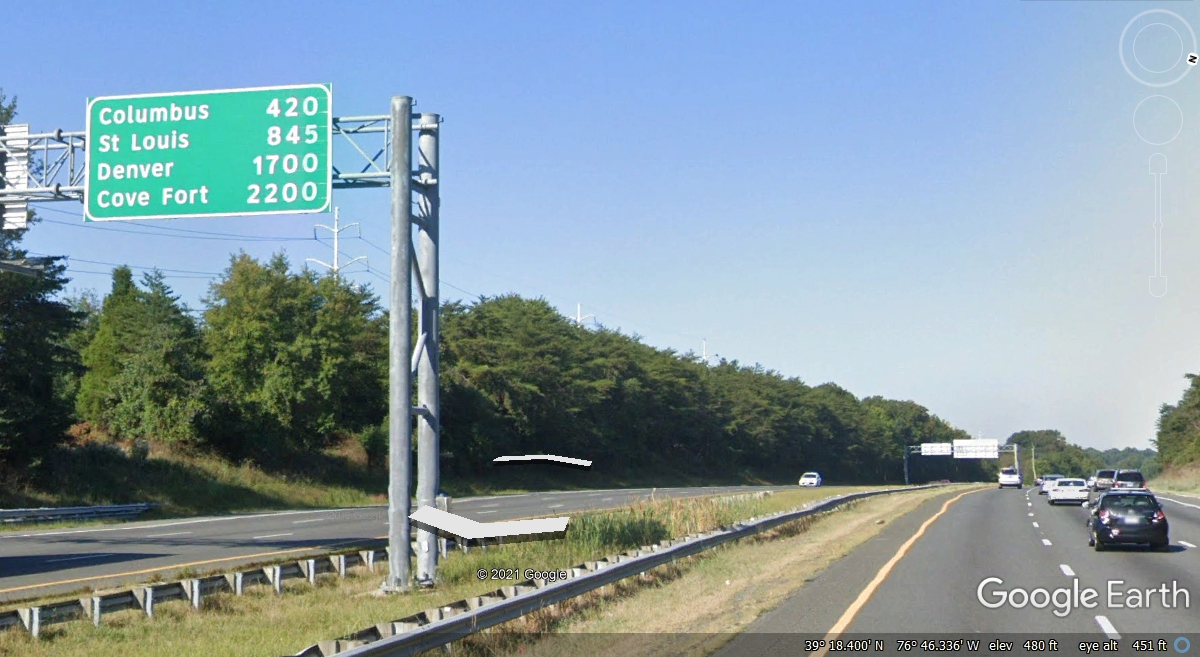
April 29, 2021: Here is a Google
Earth image I captured to update the old photo above from 2010. I also
changed the brightness of the old photo when I changed it to 1200 pixels wide.
October 5, 2010: I made it home around 11 PM Tuesday night and started unpacking the rental car. I discovered my GPS antenna was having coaxial cable problems and had to make a simple repair on Wednesday.
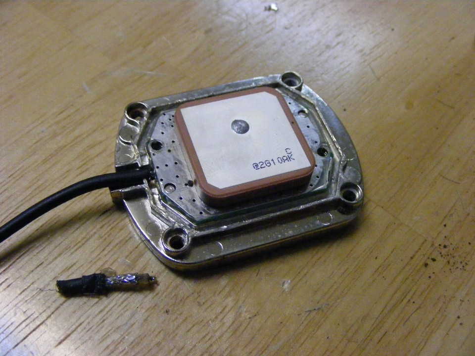
October 5, 2010: Here is the look inside my GPS
antenna after the repair and before I put the cover back on it. That short piece of
coax cable shows how the cable failed after many years of blowing in the breeze on top of
my car and the rental cars I drive. The metal plate above the insulator layer is the
actual antenna element. The drop of solder is the wire connection to the circuitry
on the other side of the board.
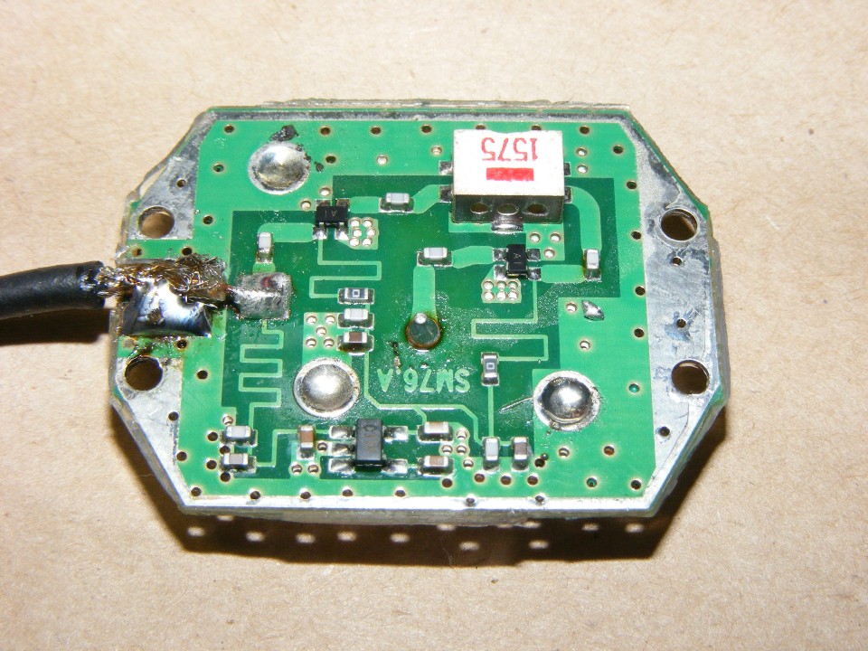
The other side of the board has the amplifier circuitry. The antenna
connection is at the center above the letters SM76A. There is a capacitor isolating
the antenna plate from the transistor near the GPS band RF filter with the numbers 1575 on
it. A second transistor RF amplifier is between the filter and the coaxial cable
output. The zigzag line coming from the cable center conductor toward the camera is
an RF choke with two capacitors to ground to insure no RF signals get into the voltage
regulator which is the black rectangle with five connections to the board. The two
larger zigzag lines help to isolate the power source from the RF circuits and tune the RF
stages in and out of the two amplifiers.
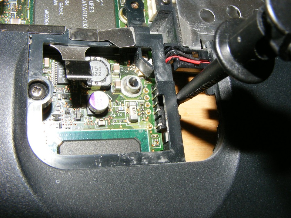
October 11, 2010: It seems I am having to repair
my most useful electronic components. Today it is the computer I use everyday and on
the road. The battery charger circuit was acting up and I did my usual research
online and discovered the problem others have had. This photo shows the inside of my
IBM T23 computer below the keyboard mouse buttons.
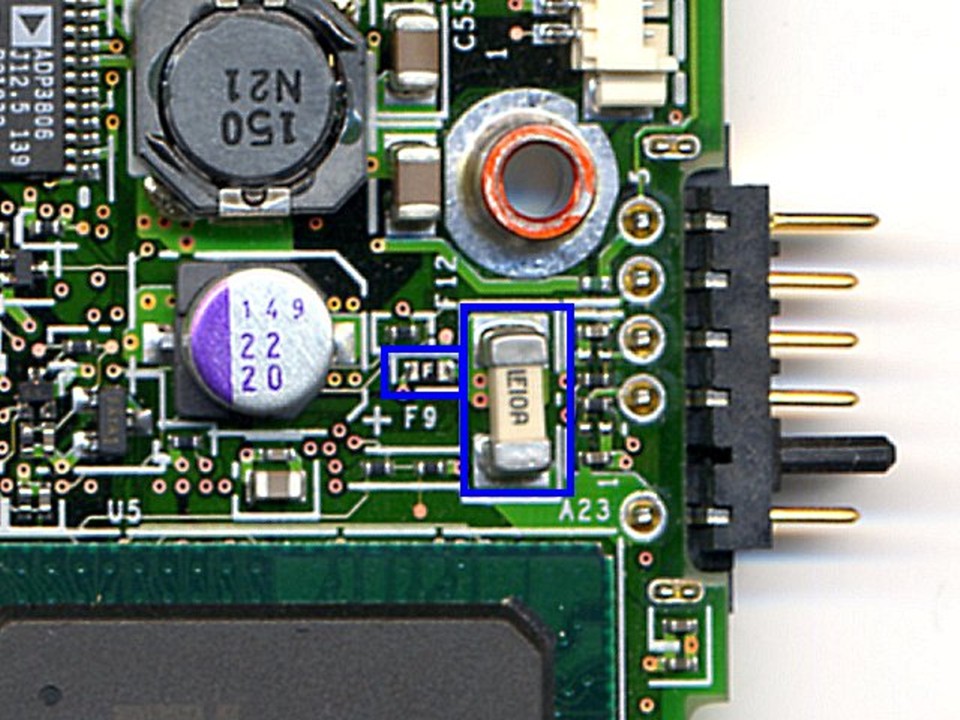
The photo below is from the internet site I found about repairing the IBM T23.
I learned about the fuses (outlined in BLUE below) that protect the computer from
the maximum current from the battery pack, and the smaller fuse between the battery
charger circuit and the battery itself. I checked those fuses as seen in my photo
above. They were both good. Which meant something else in the charging circuit
was the problem. I discovered that one terminal of the inductor labeled 150 N21 seen
below was not soldered in my unit above where the part number is 150 N22. The
charger circuit was intermittent for a long time and now it is solid again. Others
had reported this issue in the internet forum where I found this information.
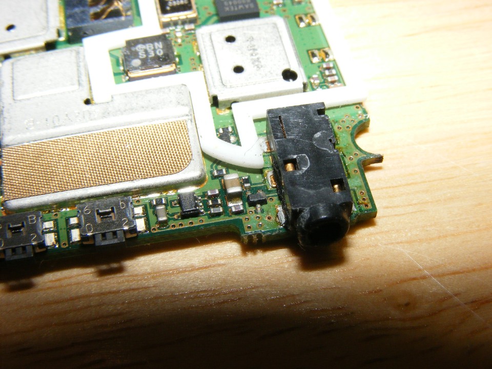
October 13, 2010: As if the electronics in my life
did not need some additional help, the Motorola V325 cell phone I use for business has
been replaced a third time. I use a hands-free headset which, when it gets a short
circuit, blows out the audio transistor that drives the ear piece. Here is a
macro-zoomed photo of the old phone just replaced. The shadow at the bottom edge of
the photo is from my camera lens. This is as close as I could get to the phone and
still get the image I wanted. That "large" black plastic piece at the
corner of the phone circuit board is the connection where the 2.5 mm plug is inserted for
the headset. There is no capacitor to isolate the output transistor from the
headphone against a short circuit. Trying to fit one there would be a real problem,
if indeed the circuit would work correctly if one were installed. The circuit
appears to be an emitter follower audio amplifier with the headphone earpiece completing
the circuit.
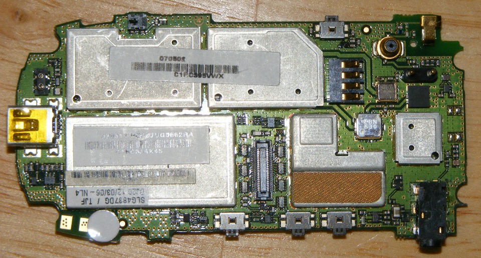
Here is the big picture of the entire cell phone circuit board. The
miniature USB charger and interface port is the yellow socket seen at the left of the
photo. The headphone jack seen in the photo above is at the bottom right corner of
the photo below. The output transistor seen above is virtually invisible in the
photo below.
| CLICK HERE for PAGE 340 | Return to MAIN MENU. |