Airport Assembly - Page 120.
May 1, 2005: This was a long day as I
continue with three more pictures on this page. My work today was in several
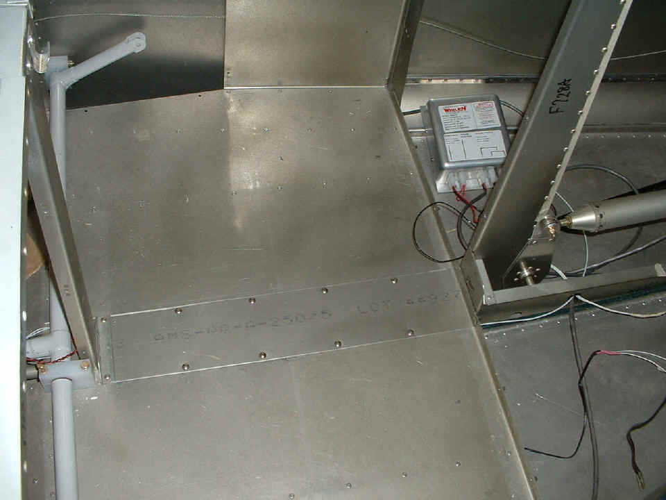
sessions totaling 9.5 hours. After completing the wiring of the strobe light power
supply, and installing that conduit down there, I could think of no reason not to close
the tunnel under the baggage area.
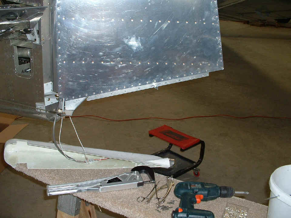
I went to the back of the airplane and put in the platenuts and the 4-40 screws
to hold the bottom fiberglass rudder cap in place. This is completed and should not
have to come off again. When it is needed to service or replace the rear strobe, the
cap can be removed to unplug the connections for the strobe and the 12-volt tail
light. The tail light bulb and the tail light strobe are both wired and ready to
test.
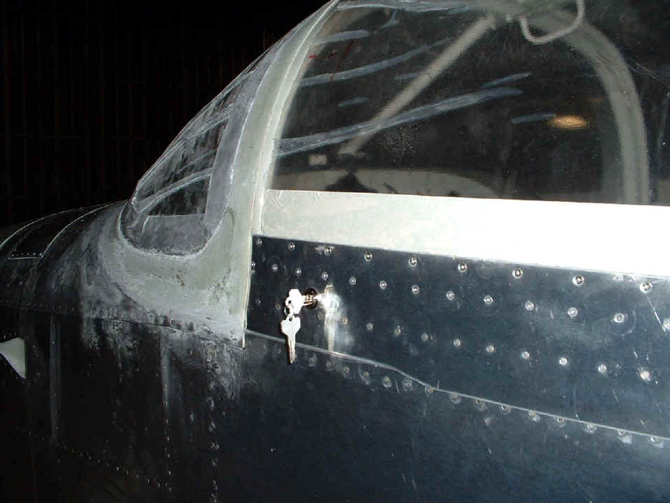
Basically, every wire behind the baggage area is connected. So, I turned
my attention to the canopy lock. That required some drilling and filing of both the
hole for the lock body, and the slot in the canopy slide rail that engages the locking tab
when the key in turned. There is an 0.040" aluminum doubler plate to secure the
lock body. I will post a picture of that from the inside after my next
session. This was the last thing I did tonight before heading home. By the
time I had everything secured and locked the hangar doors, it was 9:10 PM as I headed for
the airport gate.
Those keys are now in my pocket as I publish these pages and photos at 11:07 PM. I just watched the local weather and it will be clear and cool tomorrow. That tells me to get the last few pieces of metal primed and ready for use before I head for the airport for more work tomorrow afternoon. The official number of hours constructing the airplane now stands at 1864.5!
May 2, 2005: I worked on my commercial project for a while this morning, and did my laundry at the same time. I got a call from an industry friend who may have a job for me to fill up much of the year. I told him of my immediate plans with the airplane and the training I have scheduled. It seems the job can work in with my plans.
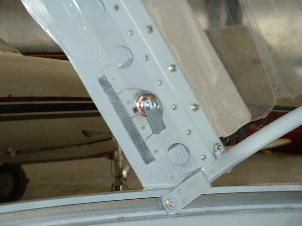
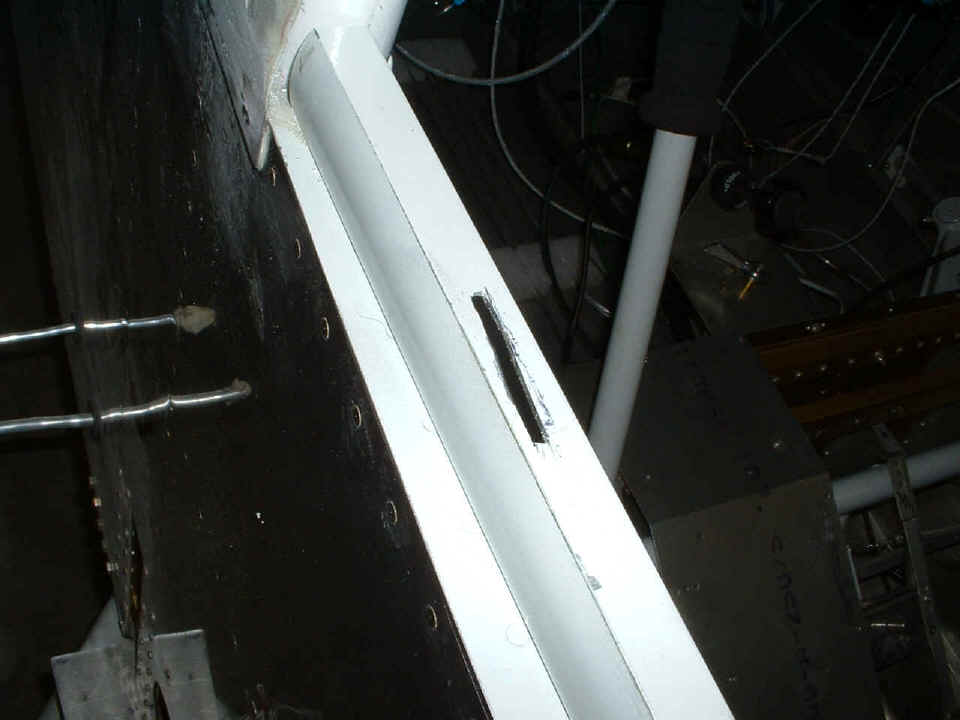
By the time I got to the airport, it was almost 4 PM. Here is a photo of
the locking tab and the doubler plate that supports it. Sorry for the bad focus.
I will replace this photo with another one tomorrow. The doubler plate is up
against the steel square tube of the canopy frame, and riveted in four places as you can
see.
This is the slot I cut in the canopy slide rail last night before my departure.
It accepts the locking tab seen in the photo above.
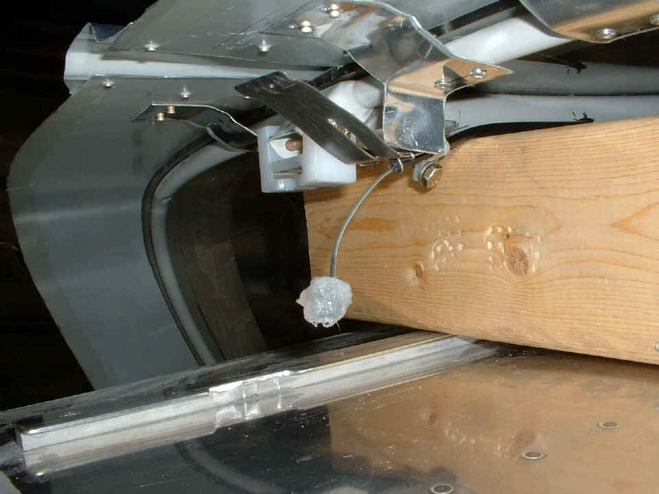
Next on the to do list was the repair of the Tugwell canopy opening cable.
It suffered from mis-alignment and needed some help. I put on a fresh glob of
clear RTV to bind the UHMW disc to the knob on the end of the cable. The
Meske canopy modification allowed me to place a board across the longerons to
raise the canopy to this position.
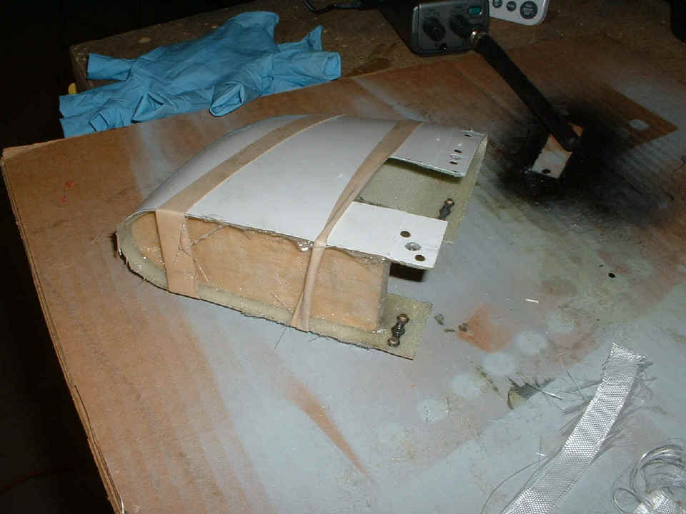
The fiberglass cap for the vertical stabilizer got a layer of glass cloth over
a block of balsa. I will be putting more layers on in another session. The big
rubber bands kept the shape I wanted while the epoxy cured.
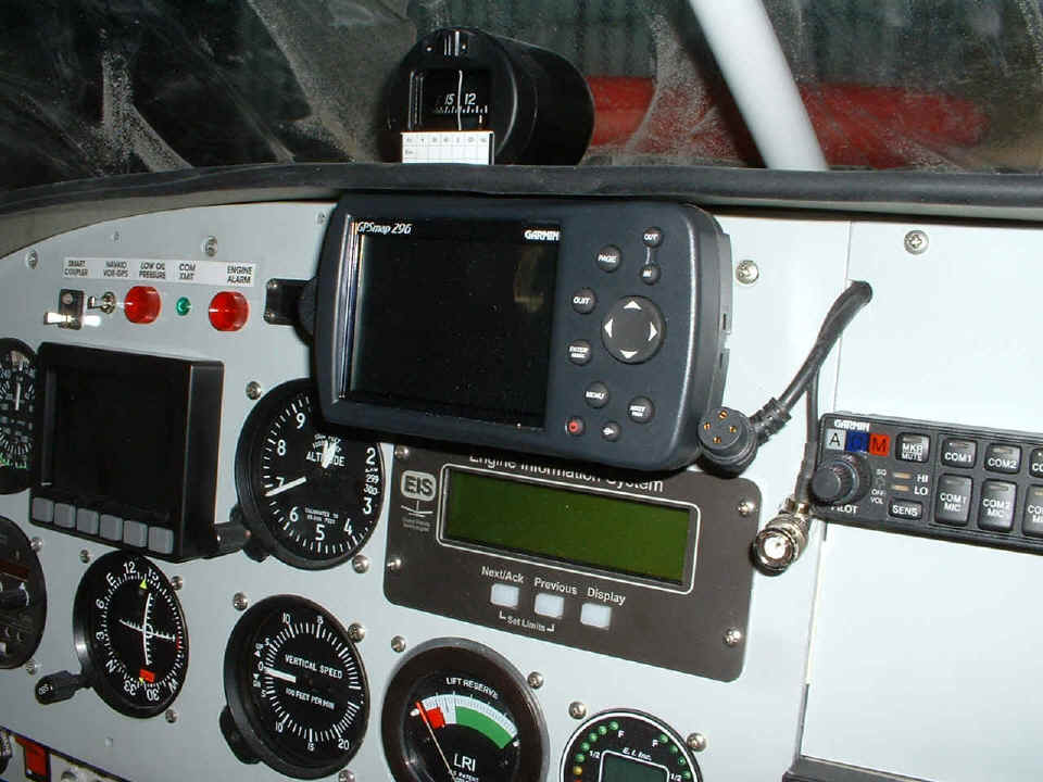
The last photo for this page is the GPS 296 snapped into the old GPS 196 mount.
That power plug is still the one for the 196, and will be replaced by the new 296
data/power cable with two serial ports, not one from the 196, when I pull out the instrument sub-panel in the next few days. This
is the first photo showing the round black rubber tubing on the edge of the forward top skin that
serves as the top of the instrument panel. I wanted to be sure I could get the GPS
in and out past this tubing which serves as padding for the edge of the aluminum skin.
This image number from my digital camera is DSCL0296, which shows my new Garmin
GPS 296 mounted on the instrument panel.
| CLICK HERE for Airport Assembly - Page 121. | RETURN to MAIN MENU. |