FIREWALL FORWARD - Page 68.
November 23, 2004: Another day with a few
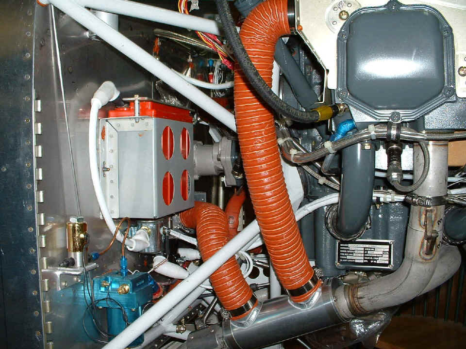
milestones to note. The heat ducts are now installed to keep me warm up high on a
cold day, etc.
And the crankcase vent a.k.a. "breather tube" is now in place. Take note of the short copper overflow tube on the right angle fitting from the
engine-driven fuel pump near the center of the photo. The white nylon tubing in the
photo below this one is connected to that copper tube.
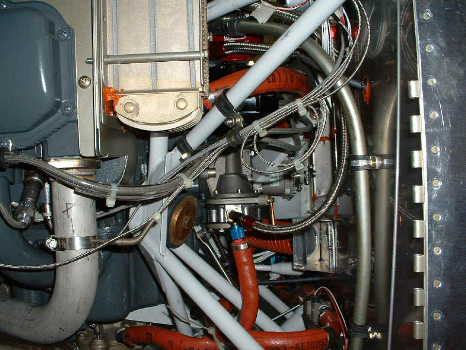
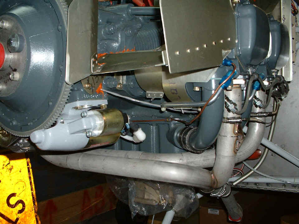
This shot below shows the white nylon overflow vent line from the fuel pump heading
down to the bottom of the fuselage at the near corner at the bottom right edge of this
photo. A vent line is seen in the center of the picture going down toward the 5:30
angle behind the red fire-sleeved fuel line and is again visible as it is lashed to the
engine mount cross bar before going into a piece of aluminum tubing with another short
piece of the nylon line that actually exits the fuselage down in the corner below that
engine mount bolt.
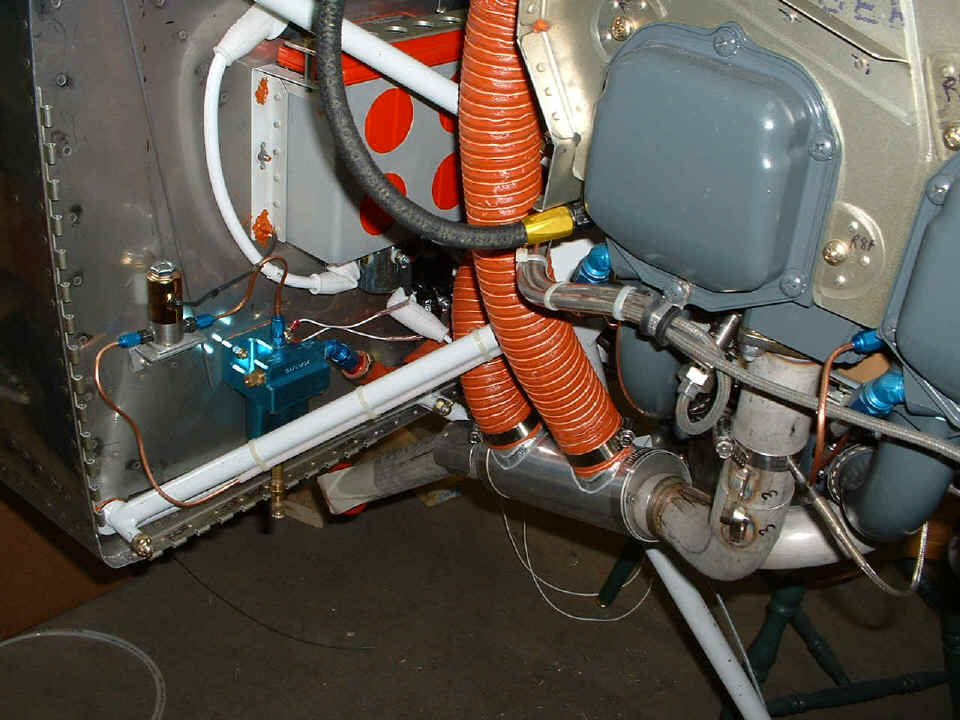
Next was the engine primer kit installation. The solenoid wires are now
routed through an extra hole I had drilled in error one day a few months ago. I
thought I would put that hole to good use and resealed it after putting the wires through
it. I put the 1/8" copper tubing inside some lengths of nylon brake line tubing
to protect it in key areas from vibrations, etc. You can see the copper tube going
into a blue AN-fitting at the right-center of the photo below on cylinder number 1.
What you cannot see is the "T-fitting" that is hiding just out of sight below
cylinder number 1. The other side of that "T-fitting" is feeding fuel to
cylinder number 2.
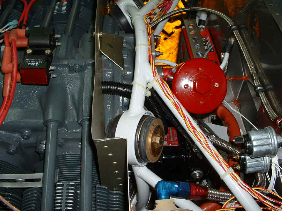
Here is the 1/8" copper primer line and fitting on cylinder number 2
showing how the copper tube comes across from the other side of the engine along the front
of the oil sump secured by a small Adel clamp. You can also see the gray wire above
the starter motor that is the crank sensor wire going under the engine and up to the
solid-state ignition system behind the firewall. Also visible in this shot is that
nylon fuel pump overflow line (from two photos above this one) in the bottom right corner
of the photo below.
This shot is showing the black corrugated cooling-air blast tube mounted just
over the magneto. Things are getting crowded back there as you can see. For
those of you who may not recognize the magneto, let me guide you. The round RED
thing in the photo is the oil filter with a hex "nut" on the top of the filter
for tightening, etc. You can see the red, yellow, and white wires running along the
steel engine mount secured with tie-wraps. At the 7-o'clock position from the oil
filter is the RED and silver label on the black body of the magneto. The oil
pressure sensor and the fuel pressure sensor are the silver "cans" with the
connections at the bottom right corner of the photo below.
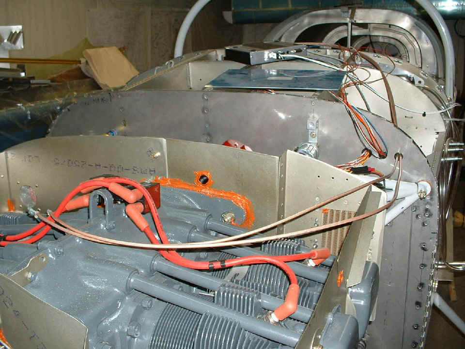
And the last shot of the day shows the top of the engine with the entry port of
the magneto blast tube clearly visible with RED RTV around it on this side of the back
baffle plate to dampen vibration of the tube in the 11/16" hole I put into the back
baffle. Those two beige coaxial cables you see come from the solid-state ignition
module and will eventually be connected to the high-voltage modules you see on top of the
engine. I have to drill some holes for them to pass through the back baffle.
The ignition control module is the black and silver box laying up on the fuselage.
I have been thinking about how I am going to mount the unit to make it easily
serviceable. That aluminum plate with the blue plastic on it is probably going to be
used to mount the module almost directly below where the plate is sitting on the under
side of the two ribs that are supporting the aluminum plate in this photo.
I also took some time to straighten a metal mounting plate for the wheel pants of the left main landing gear. I tripped over that a few weeks ago and bent it slightly. I used a bottle jack under the "main wing spar carry-through" to lift the landing gear clear of the floor, allowing me to remove the left wheel to straighten the mounting plate. That's all for today, Luis. Good night all....zzzzz.
| CLICK HERE for Firewall Forward page 69. | RETURN to MAIN MENU |