FUSELAGE CONSTRUCTION - Page 33.
December 21, 2003: The electric fuel pump is
on its way and should be delivered Tuesday. When it arrives, I can finish the fuel
line and brake line routing to their firewall connections. I have been doing some
other things in the past few days to clean up my remaining tasks. While the tail
section was mounted to the fuselage, I fabricated the steel links to tie the rudder
pedals to the control cables and had positive rudder control. I also routed the
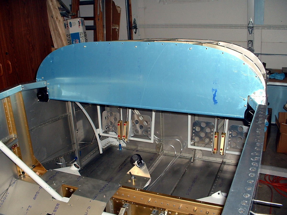
elevator trim cable through the fuselage and calibrated the neutral trim tab position to
4.5 turns from the stops (1/2 of the 9 turns it will make). You can see the trim
knob in the picture below with a piece of masking tape on it that I used to count the
total number of turns from stop-to-stop. I finally finished the last piece of the
LEFT elevator after spray priming the steel trim cable attach bracket, then riveting it to
the access plate on the bottom of the elevator. Sorry, no picture of that today.
There is a protective conduit hanging down behind the left side of the control
panel. It has another 1/4" plastic tube in it coming from the static ports
mentioned on page 32. You can also see the BLACK
fresh air vents in the picture above at
both sides of the control panel. I started on the air scoop that brings the air from
the outside to these interior vents. The scoop has an aluminum doubler skin to
insure that it gets solidly riveted to the outside skin. I fabricated that doubler
from a plain sheet of aluminum tonight and cut it out using my scroll saw.
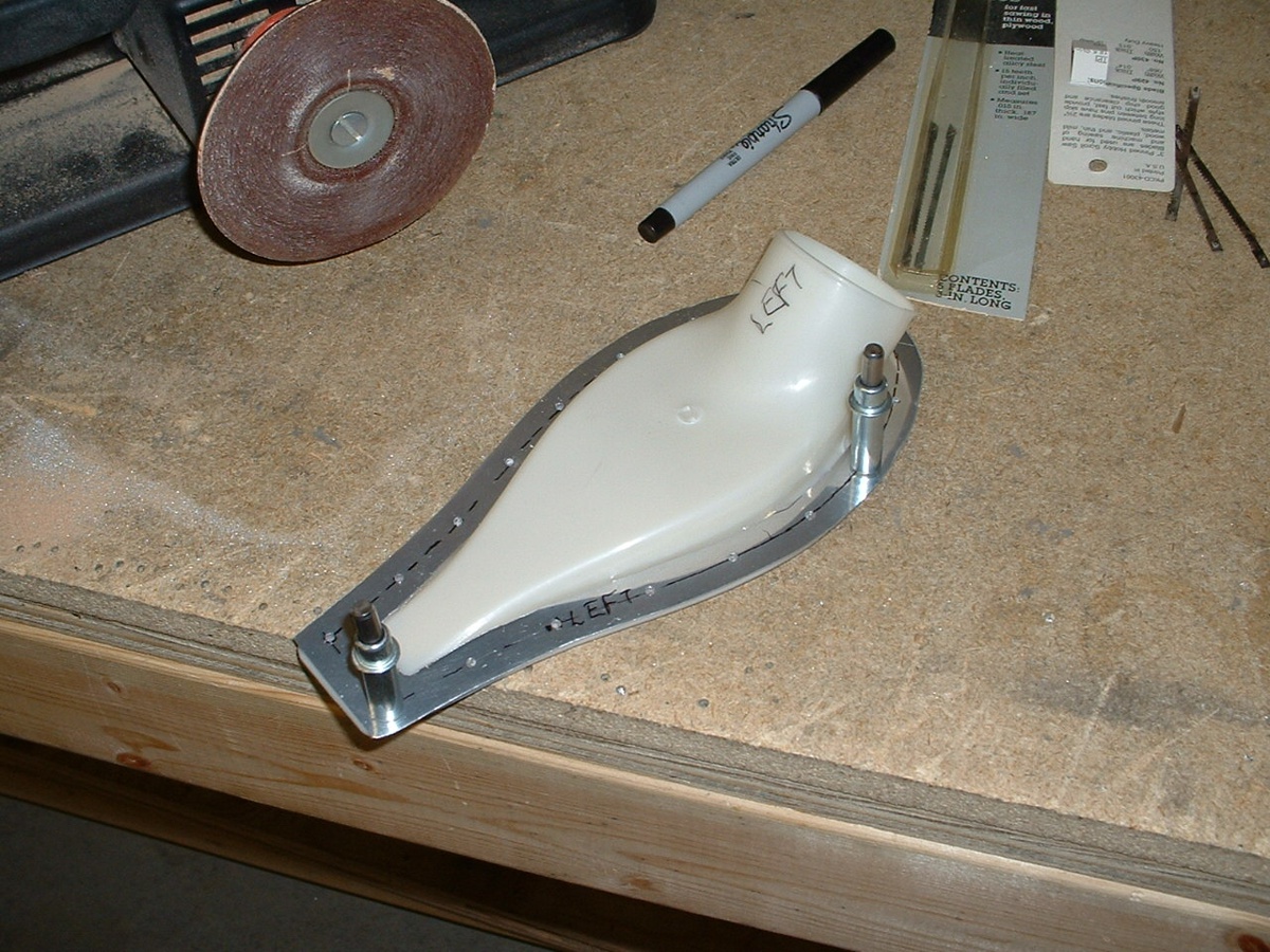
I have drilled the rivet holes through the plastic and the aluminum doubler.
The next step will be to match-drill the assembly to the outside skin. More
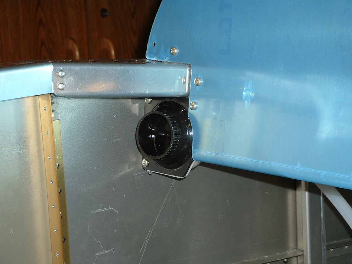
about that later. Here is a close-up shot of the LEFT air vent at the bottom of the
control panel. There were four rivet holes in the side skins which have now been
filled. I riveted the attach bracket to the side skins for the vents. You can
see two screws on the LEFT side of the vent below. They are anchored in the bracket
that I riveted to the side wall. You can also see where I trimmed off part of the
vent to fit in the space next to the control panel.
I have to acquire some blank aluminum panels to actually mount my flight instruments. I am going to use the panel above as a structural member to hold the sub-panels with the actual flight instruments and engine instruments on them. That way, I can easily service the equipment on the panels without climbing UNDER the control panel, etc. Eventually, the panel above will have large areas cut out of it to allow clearance for the flight instruments, radios, etc. I will be removing the control panel and support ribs when I complete the vent work. This will allow me the access I need to finish the fuel and brake line plumbing around the rudder pedals.
The current labor count is 959.0 hours of work on the airplane. Total time for the project including all prep work: 1021.7 hours.
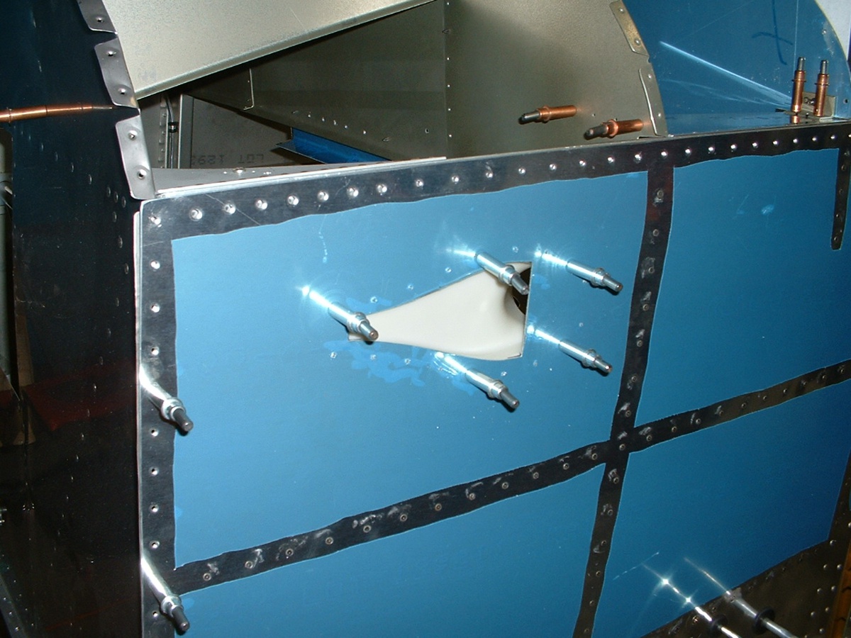
December 22, 2003: This day found me finishing up
the scoops and match-drilling them to the side skins. I also added the
throttle/mixture/carb heat/propeller control panel to the bottom of the main panel.
You can see those things in the two pix below. Add another 3.3 hours of work.
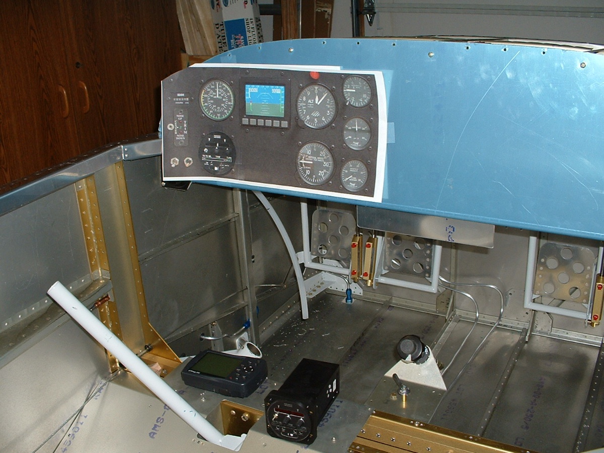
The EFIS device is the Dynon unit that David Edgemon has in his panel. It
does so much electronically, there is no need for a vacuum system. Some of the
functions are also emulated in my GPS 196. And of course, you can see my first paste
up of a panel idea. The paper print-out is to scale. You can see my Garmin 196 GPS
and the NavAid Devices wing leveler control in the photo above. I had to consider
the space behind the panel to accept the devices. This will be an ongoing process as
I acquire more instruments.
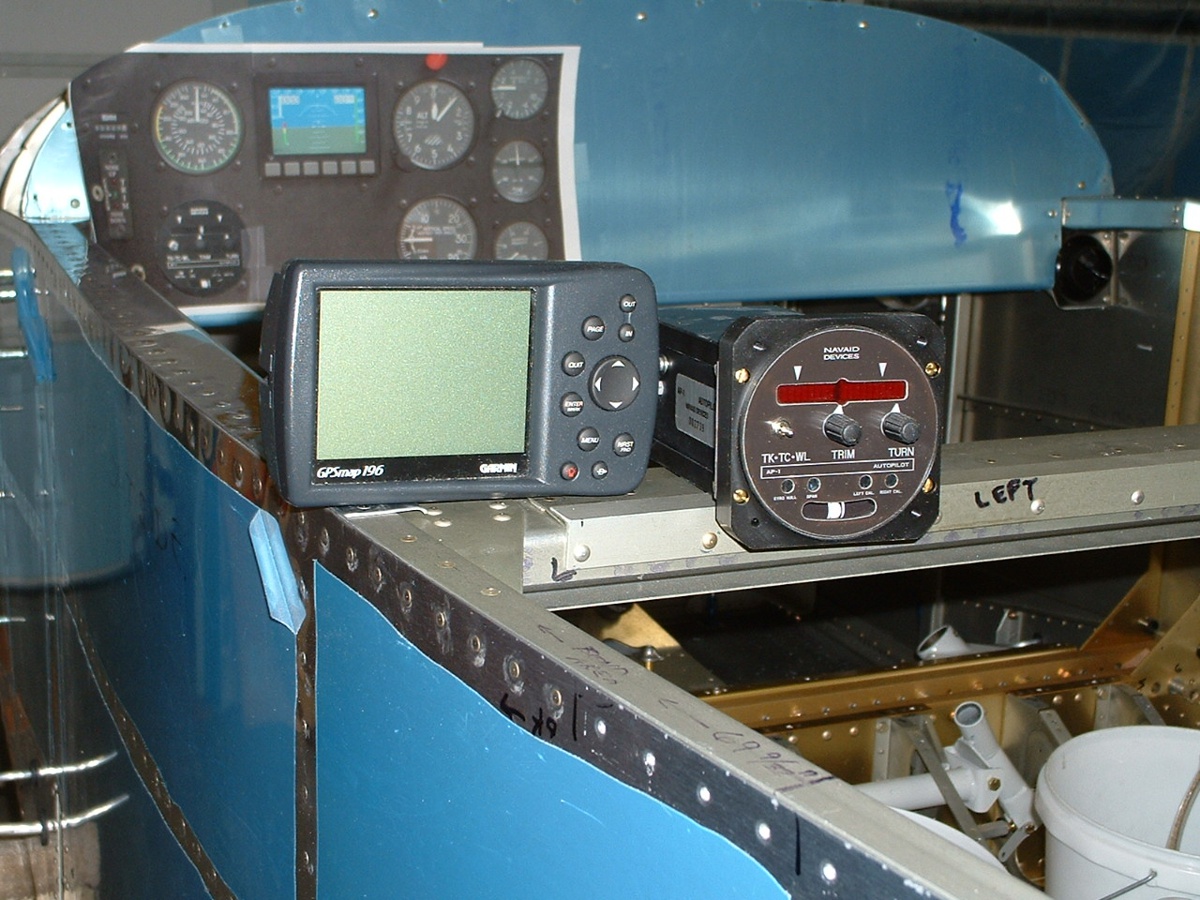
I put the GPS and wing-leveler controller up on the crossbar for a better
head-on photo. You can see the skid ball is a traditional gravity device, whereas
the 2-minute turn indicator is an LED bar-graph display derived from the gyro inside the
device. The GPS serial output will connect to the Navaid wing leveler to provide
tracking of a course programmed into the GPS 196. The GPS serial data coupler is built
into the wing-leveler controller.
| CLICK HERE for fuselage page 34. | RETURN to MAIN MENU |