EMPENNAGE KIT - Page 2.
(This page was updated again on September 3, 2017 with improved photo quality.)
Here are the first pictures from my new digital camera. I bought the Fuji FinePix 2650 with 3x optical zoom lens. I realized that the high-resolution photos were making the dial-up load times too long, so I gave in and let Front Page 98 do some compression, and it shows in the pictures. Revised the resolution of photos on 1/15/03.
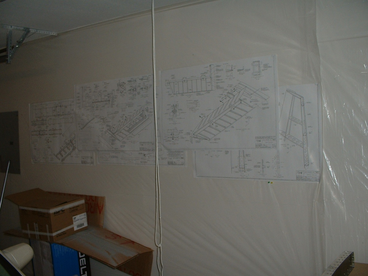
The large-sized plans I have been using are stapled to the garage wall. The
plastic sheet attached to the wall protects the drywall from flying dust, spray, etc.
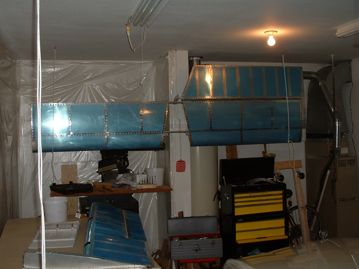
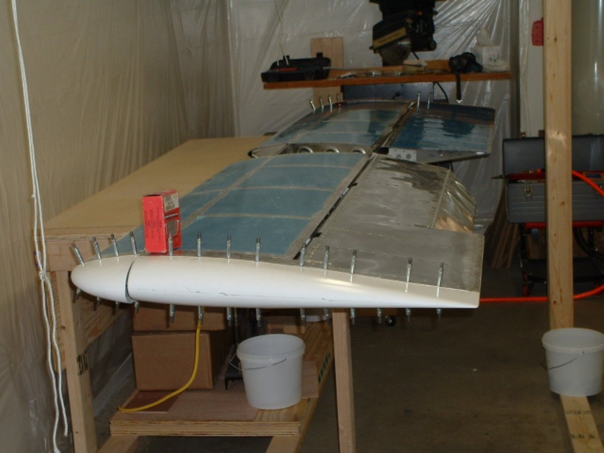
The horizontal stabilizer with the right elevator temporarily attached is
hanging from the ceiling at the north end of the garage. The rope hanging from the ceiling
in the foreground is for those times when I need an extra pair of "hands" to
hold on to something too big to sit on the work table. That yellow and black
roll-around tool box came from Wal-Mart and I stocked it with all the aircraft specialty
tools.
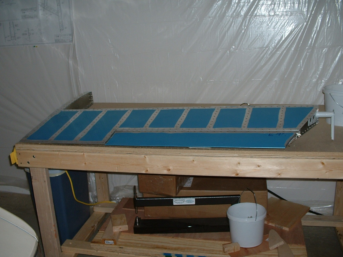
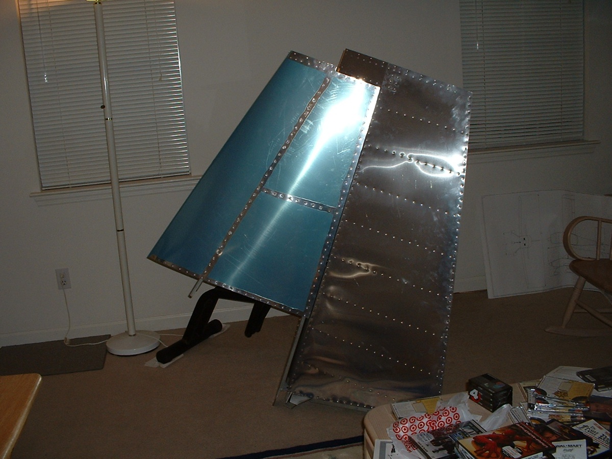
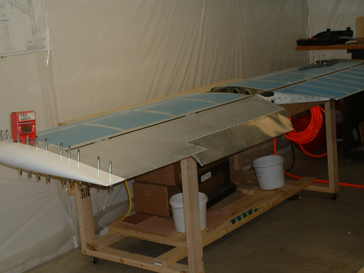
Here is the left elevator with the protective blue plastic film still in place
to minimize scratches to the aluminum skin. My C-frame for dimpling skins is down
below the work table on the storage shelf. A bucket of clecos is down there and
another bucket of them are up top.
October 14, 2004: I have gone back into my
photo archives and brought out some old photos that were not on the original version of
this web site. Now that I have plenty of server space, I have replaced the photos
that were compressed too much and I have added some "new" photos showing some of
my mistakes in hopes that others will avoid some of the pitfalls. These photos were
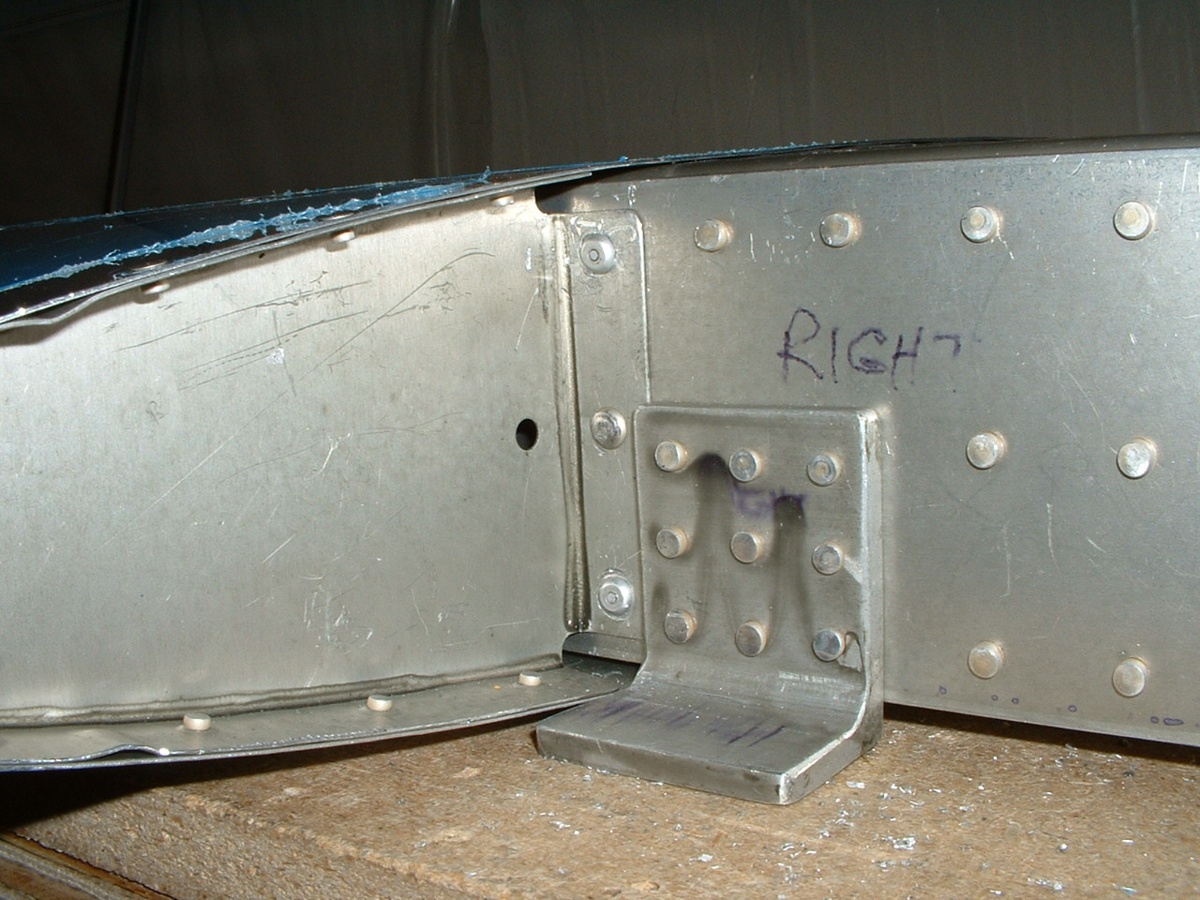
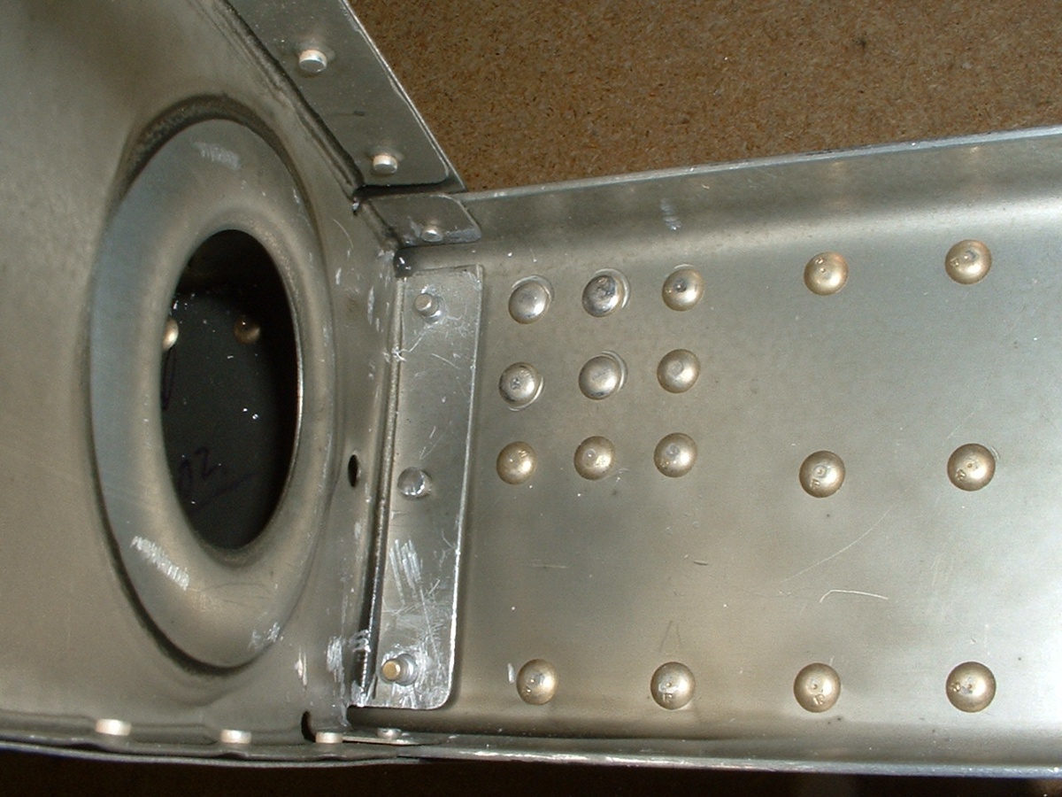
taken December 29-31, 2002. The first one shows how I
had to use Cherry Max pop rivets in a few places where I had
no success putting in hard rivets. The top and bottom rivets are replaced on the
RIGHT side nose rib flange to the front horizontal stabilizer spar.
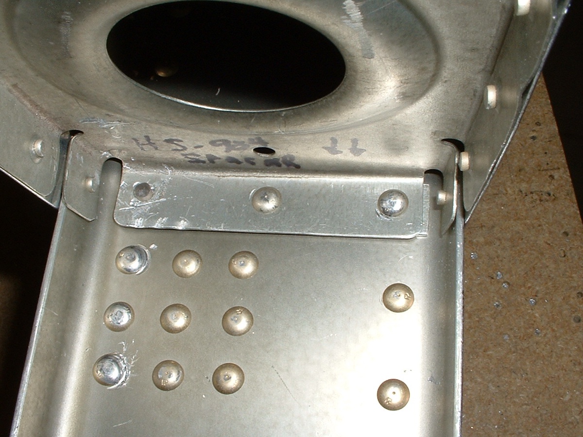
Here is the backside of the spar from the photo above. The central shaft
of the Cherry Max rivet is visible at both locations on the rib flange. I was able
to squeeze all the rivets except for those in the corners. Knowing what I do now, I
would have riveted in the nose rib and the main rib to the spar before beginning to put
the skin on the assembly. That would have given my rivet squeezer the room it needed
to do those "corner rivets" the proper squeeze angle they needed.
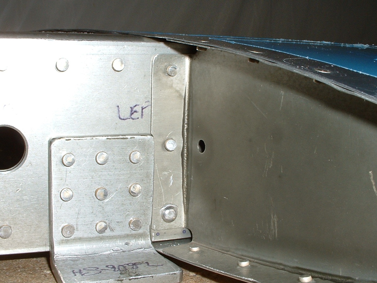
This one shows the front spar on the LEFT side nose rib of the horizontal
stabilizer. I only needed to replace ONE bad hard rivet on this side. For you
beginning builders, notice that there are NO HOLES in the "foot" of the aluminum
angle in these photos. Each one of these angles gets TWO holes later when it is time
to "DRILL IN ASSEMBLY" when mounting the horizontal
stabilizer to the fuselage.
Here is the back side of the LEFT inside rib of the horizontal stabilizer.
No, you are not imagining things here, there is one hard rivet that is put in from
the opposite side of the spar. I was able to get this one in better from the other
side -- NO Cherry Max rivet here. As you can see, I had some rivet gun
alignment problems and ended up with some "cup marks" on some of these
locations. Not all the rivets could be squeezed.
The vertical stabilizer with rudder attached is sitting in the living room. I
normally have it up against the wall between the two front windows, but pulled it out into
the room for this shot.
I hope to finish all the metal work this weekend and may put the fiberglass tips on things later, or not. The wing kit is due in early January.
December 31, 2002: I cut the fiberglass tips
for the left elevator and the left side of the horizontal stabilizer to fit today.
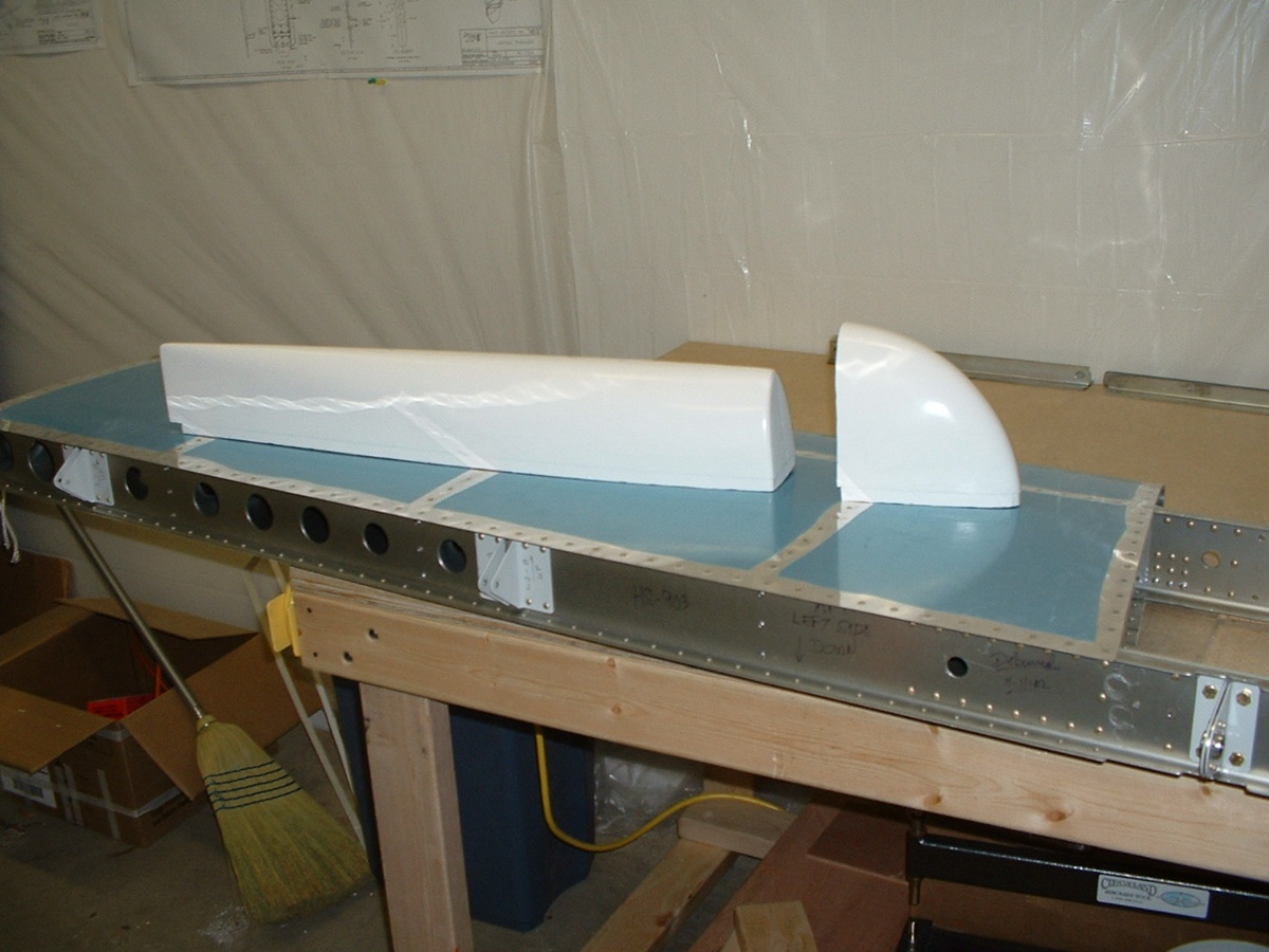
January 2, 2003: I trimmed the other
fiberglass tips for the horizontal stabilizer and elevator, then match-drilled all four
parts. I also started to fabricate the balsa plank to fit the back side of the left
horizontal stabilizer tip.
("New" old photo October 14, 2004)
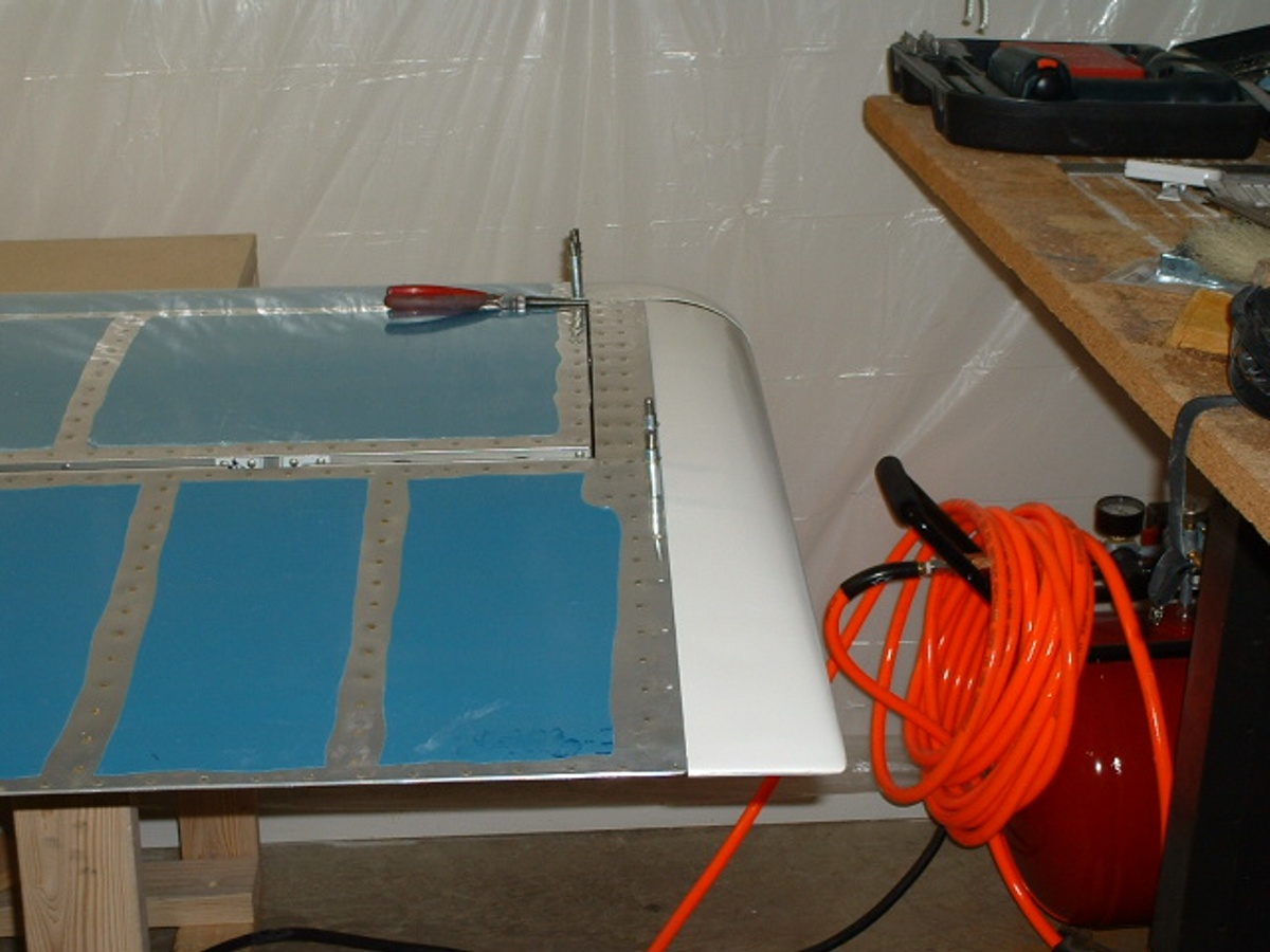
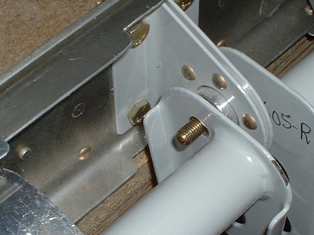
And here is a testimonial for doing things the right way the first time. I
pondered over the instructions about how far to set the rod end bearings from the elevator
spar before drilling the 1/4" holes in the torque arms. I should have tried to
move the elevators up and down before drilling these holes. That would have told me
that more CLEARANCE adjustment of the rod end bearings was needed to clear the elevator
skins from rubbing on the back side of the rear spar of the horizontal stabilizer (HS).
Notice the elongated OVAL hole in the photo below. It looks like that since I
had to drill it a second time after making the adjustments to the rod end bearing to
prevent the elevator skin from rubbing against the rear main spar of the HS. I could
not put a nut on the bolt and turn it when the first hole was drilled in the wrong place.
(Oct 14 note: This got fixed later in the
project.)
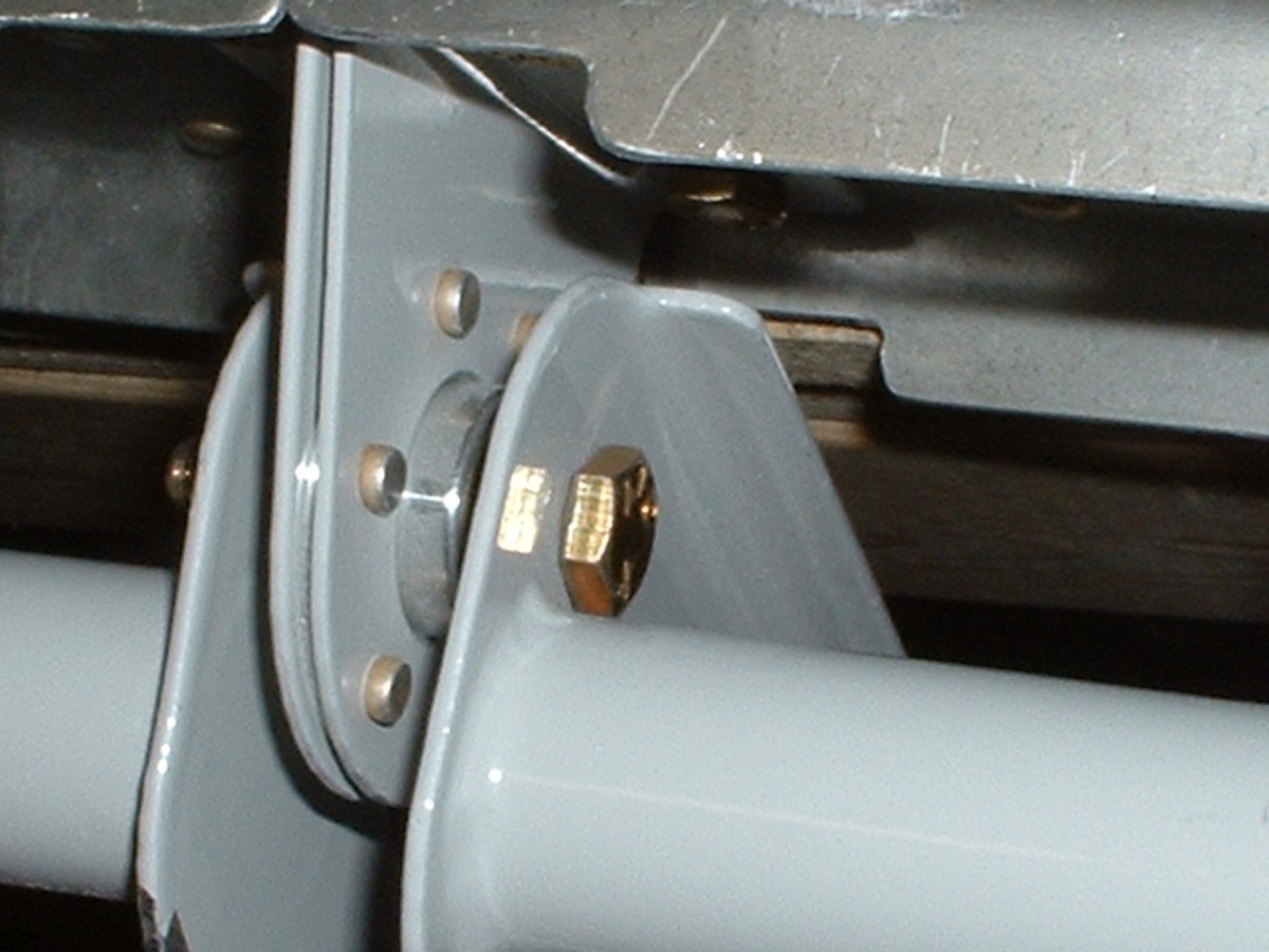
Here is the other end of that same bolt on the other elevator torque arm.
The head of the bolt would not turn in the first hole before I "elongated the
hole after the rod end bearing adjustment. The bolt head is hiding the view of the
oval-shaped hole.
| CLICK HERE for Wing Kit - Page 3. | Return to MAIN MENU. |