Newport, Washington Six-Pac Installation
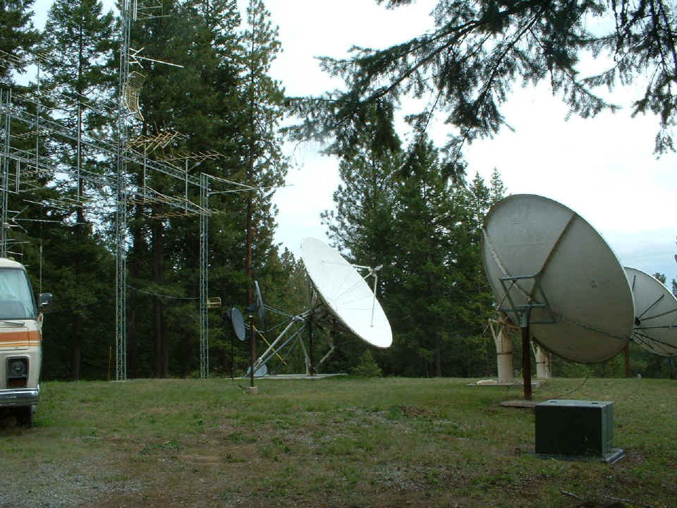
September 22, 2004: The Newport headend is
on a nice hill with Rohn towers connected together to mount the local antennas.
There are many S/A and other types of satellite antennas on this site. The
independent owner of the cable system is Keith Antcliff, who is
also a pilot.
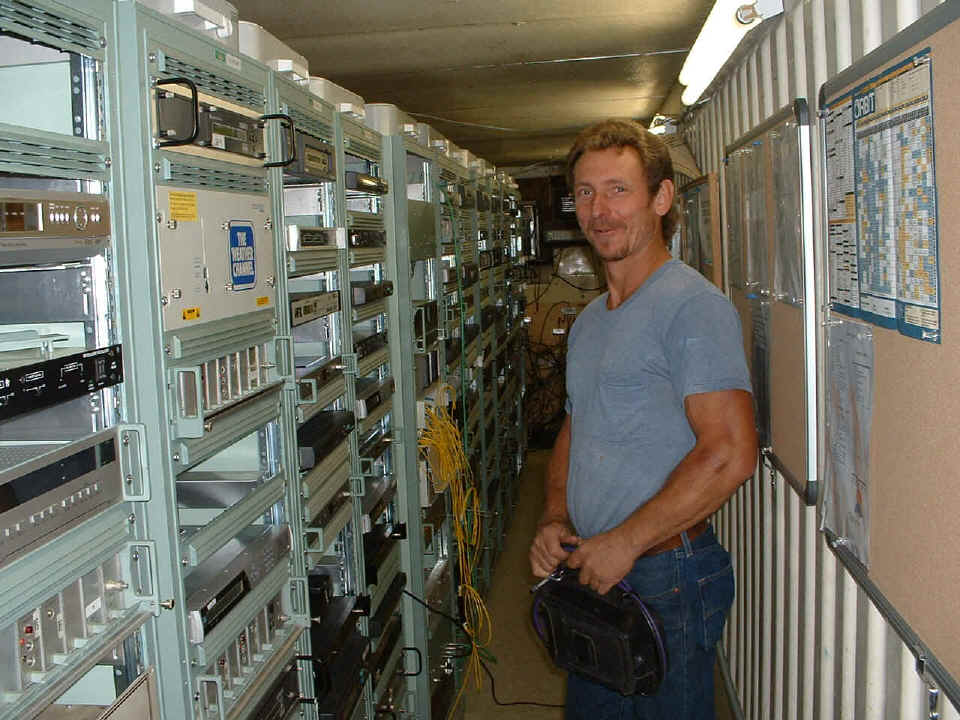
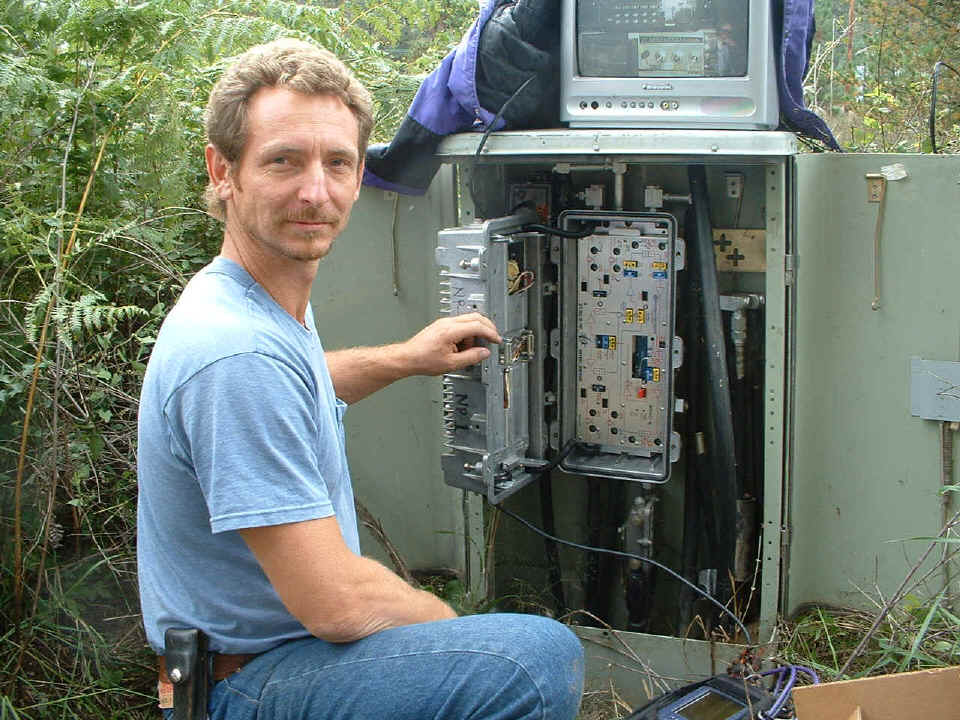
This is the system technician Mike Dale in the headend when we were checking
signal levels before starting the amplifier installations. I told Mike he has one of
those familiar faces, in his case, he looks like the cowboy movie star Lee Van Cleef. You may remember the actor from the Clint
Eastwood movie "The Good, The Bad, and The Ugly".
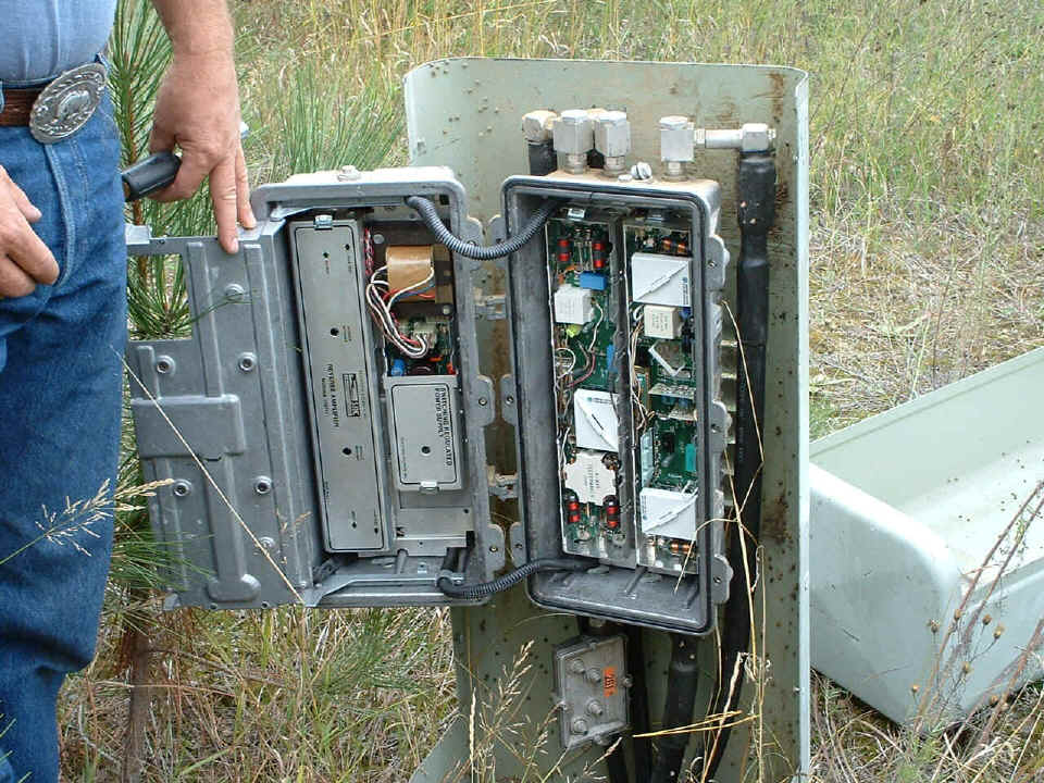
This is the first amplifier down the hill from the headend before the Six-Pac
amplifier installation. This is the third amplifier from the power supply
location. I measured 54 volts AC with the original SA push-pull trunk amp installed
with a power-doubled bridger, ACM module and an original S/A return amplifier. This
location does have BBI diplex filters installed.
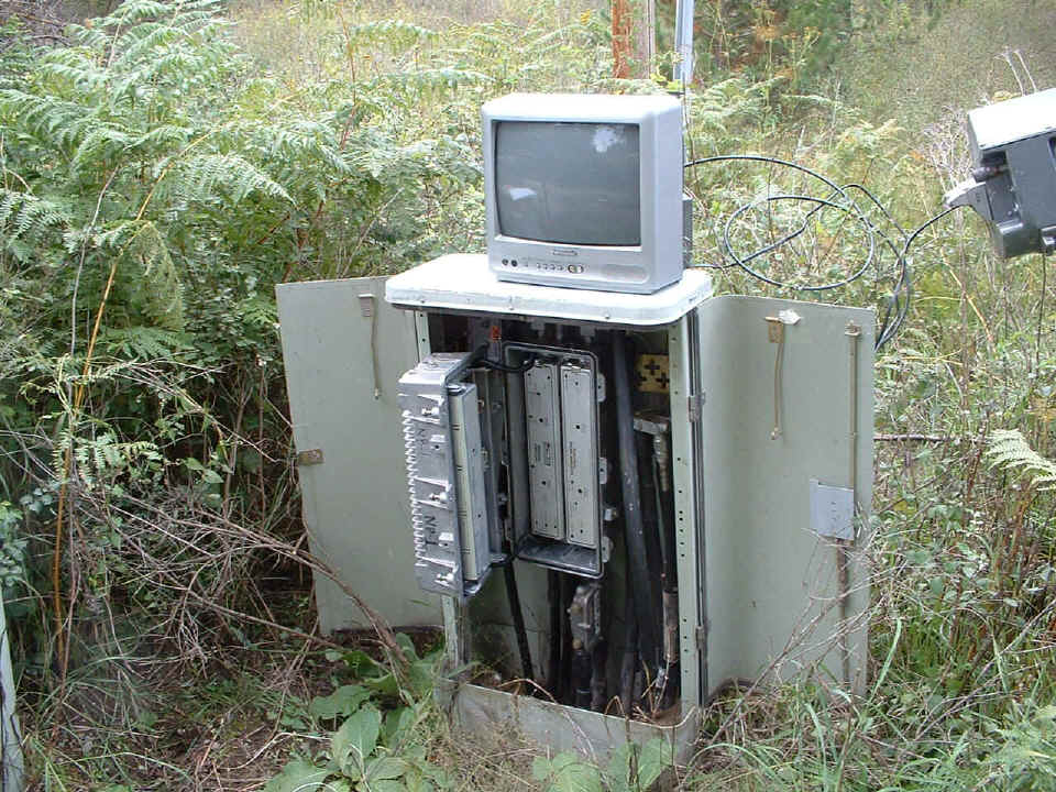
After the Six-Pac is installed, AC voltage is 52 volts, all forward and return
RF levels are within 1 dB of predicted values. The TV set is tuned to channel 11
with a camera looking at a spectrum analyzer and signal level meter, both tuned to show
the return path signals at the headend. When we put in the first amp, Mike noticed
that the noise floor on the spectrum analyzer was lower and a bit flatter. I taught
him a better technique for reverse amplifier pad selection that provided the improved C/N
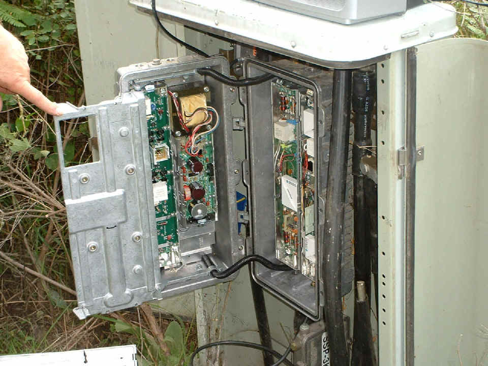
for the return path. The photo shows the RED shunt with AC power coming into the
amplifier from the output trunk port with no power going to the feeder lines since there
are no line extenders off this amplifier. Mike is using the same GI 600 MHz tap we
saw at Union, Washington as a test point at this location. The 750 MHz carrier was
measured at the expected level on the amplifier test points, but was down slightly on the
26 dB tap port.
At the second amplifier location, the AC line voltage with original modules now
reads 49 volts. We previously went to one of the line extenders fed from this
amplifier and measured 46 volts AC there after the first Six-Pac amp was installed down
from the headend. The amp below is off a trunk splitter from the output of the first
amp location and feeds an area south of the main part of town.
When the second Six-Pac was installed, it blew the fuse at a splitter back up the trunk toward the power supply. It had an intermittent AC short circuit at the green wire soldered to the circuit board on the trunk output side of the D-connector. This amp location is a short side trunk cable that is fed from a splitter on the trunk output of the first amp from the headend. It is FOUR amp spans from the power supply.
| Return to other travels menu. | Return to main menu. |